GeistHaus
log in · sign up

(unnamed stream)

Part of wordpress.com

stories
Who wrote the first computer Easter Egg?
Uncategorized
An unexpected email I hadn’t looked at Easter Eggs since 2017 when I wrote about what may be the first Easter Egg in an arcade video game, but that all changed when I received an email from Kate Willaert letting me know she had linked to my story in a recent video about early video … More Who wrote the first computer Easter Egg?
Show full content
from “Racing the Beam” page 59.
An unexpected email

I hadn’t looked at Easter Eggs since 2017 when I wrote about what may be the first Easter Egg in an arcade video game, but that all changed when I received an email from Kate Willaert letting me know she had linked to my story in a recent video about early video game Easter Eggs and asking if I could help her out with another project.

The video she sent is wonderful and led me to read some of her other recent work including a fantastic article about the 1973 game Moonlander which touched on some of the same areas I’ve been looking into lately, having to do with early games for the DEC PDP-8 and PDP-11 and which I hope to write more about soon.

In her email, Kate mentioned something I had pulled out of the Wikipedia entry on Easter Eggs, namely that the first Easter Egg may be a command for the very early text editor TECO which dates all the way back to 1962 and was written for the PDP-1, one of the first interactive digital computers. Could the first Easter Egg date back that far? It turns out she had interviewed the creator of TECO, Dan Murphy and asked him about the Easter Egg, but he said it was added after he left, “likely by one of the hackers at the MIT AI lab”. (note that the word “hackers” in this case refers to the earliest independent computer programmers as documented in the classic book by the same name).

Could it be that no one had ever bothered to track down the author of the first Easter Egg?

And so we finally get to her request, which was: since I have a working PDP-11, could I reproduce the Easter Egg and send her a video? I let her know I would try my best to help her in this noble pursuit. After all, this could be the first Easter Egg ever.

The next day I sent her this email:

Hi Kate,

I’ve spent a few interesting hours on this. There’s more work to do. I suspect some of the lore around this is wrong. I was able to reproduce the egg on a simulated PDP-10 (see attached image). Based on this and other things I’ve read so far, I suspect that the Easter Egg is technically in the TOPS-10 (PDP-10 operating system) MAKE command. Not in TECO itself. I don’t know yet when it was introduced. I’d like to find the source code and then look back for the earliest version available. I suspect it did not exist on the PDP-6. If I’m right, that would put it no earlier than 1967. I would note that the phrase “Make Love Not War” probably wasn’t in use in the early 1960s: https://en.wikipedia.org/wiki/Make_love,_not_war. I hope this helps,

                           -EdF

I had reproduced the Easter Egg using an amazing program called SIMH which is supported by the Computer History Museum. SIMH is a general purpose simulator that can emulate DEC machines from the PDP-1 to the VAX, the Altair 8800, and many other popular computers from the 1960s and 1970s. You can set up your own simulated PDP-10 by following the instructions here: https://www.filfre.net/2011/05/tops-10-in-a-box/ and not only reproduce this Easter Egg but also play the original text Adventure while you are at it. (If you really have time on your hands you can read the Oral History I did for the Computer History Museum back in 2014. It has a few stories from my early days at Microsoft).

Finding the source code

Kate seemed happy, and encouraged me to keep digging. We still had no idea when the Easter Egg was added or by whom. I guess I needed to look into the source code for TOPS-10. Would that even be available? Pretty quickly I stumbled on an old forum discussion which, in retrospect, held some really important clues, but they were mixed in with just as many red herrings.

The discussion mentioned a file called COMPIL. Perhaps that’s where I needed to look? Eventually I figured out the full name of the file was COMPIL.MAC (a macro assembler file) and I found that file in a collection of TOPS-10 source code from the mid 1970s. In the file, sure enough, I found the code that implements the Easter Egg. It wasn’t very hidden. In fact, it was well commented and there was even a comment saying not to remove it!

I love the note at the end about leaving the “HACK IN FOR SALES DEMOS”. The DEC guys tried so hard to be cooler than their competitors at the straight-laced IBM.

This was progress, but the header at the top of the file showed how far I still had to go:

This file was from July, 1976. I needed something older. Much older.

Closing in

Hours of additional searching finally led me to an obscure website, sky-visions.com, where not only could I learn how to make kites, but I could also look through the source code for some of the oldest known versions of the TOPS-10 operating system. Nestled among these pages was the much earlier version of COMPIL.MAC I was looking for, dating all the way back to the 7th of July, 1971.

The Easter Egg code was identical in this file to the first version I had found. It wasn’t immediately clear how to proceed.  I exchanged a few emails with the website owner, Richard Cornwall, but he didn’t have an earlier version of compil.mac and didn’t know where I might look for one. At this point I started to pay more attention to the rest of the comments in the header. As you can see, it says the file was converted from an even earlier file in 1968 by “R. Clements” and that earlier program was originally written by “William Weiher” at the Stanford AI Lab (NOT the MIT AI Lab that TECO Author Dan Murphy suspected).

That reminded me of something I had seen in the forum posts I mentioned earlier in this story. I went back and reread the posts and found this interesting comment:

Could “/Rcc” be “R. Clements” from the comments in the compil.mac source code? If so, that would point the blame or glory for the Easter Egg squarely at one person: William F. Weiher and set the date for his actions no later than November 1st, 1968. We were getting close… I decided to send Kate an update.

Victory!

A few days later I found a fantastic early birthday present from Kate waiting in my inbox. It said:

And so we finally know who wrote what may be the first Easter Egg in history: William Weiher, sometime between October 1967 (after he finished his Elvish alphabet routines) and the end of October 1968, when it was ported to TOPS-10 by Robert Clements.

Of course, there may be an even earlier example of an Easter Egg out there. Perhaps by some IBM prankster in the 1950s? I hope this article inspires someone to dig deeper and find more Easter Eggs before they are forever buried beneath the sands of time. I’m sure they will have even more fun than Kate and I did on this wonderful Easter Egg hunt.

(at this point I strongly encourage you to read Kate Willaert’s companion article which includes her side of this adventure and a complete interview with William Weiher).

racing-the-beam
edfries
http://edfries.wordpress.com/?p=1949
Extensions
Finding the First Videogame ROM
Uncategorized
These days it’s not unusual to read stories about game collectors buying rare game cartridges for thousands of dollars. But what is in those cartridges? Typically just code and data stored in one or more ROM (Read Only Memory) chips. In my last story, Fixing Gran Trak 10, I documented the first arcade game to use … More Finding the First Videogame ROM
Show full content

These days it’s not unusual to read stories about game collectors buying rare game cartridges for thousands of dollars. But what is in those cartridges? Typically just code and data stored in one or more ROM (Read Only Memory) chips.

In my last story, Fixing Gran Trak 10, I documented the first arcade game to use a ROM. The problem was which ROM? Was it the one we found over and over again with the number 74186 or was there an earlier, much rarer ROM with the number 74181? This idea was championed by one of my collaborators, Andrew Welburn, and supported by several pieces of obscure but provocative evidence: A track that appeared on an advertising flyer but not any shipping game we could find; A schematic for a an early development board called “proto-b” that no one had seen; A snapshot taken by one of the original game developers of his kids playing an early version of the game over 40 years ago.

I waited as long as possible before publishing that story. I talked to everyone I could think of, but eventually I had to admit that I was stuck. Maybe by publishing I would get the word out and someone would step forward. I pushed the publish button and waited. I was still waiting six months later.


An Unexpected Message

Chat2

Okay, a few pieces of context here. First, John Hardie is an old friend and co-founder of the National Videogame Museum. He knows his stuff. Second, by Portland, he is referring to the Portland Retro Gaming Expo where I would be later that evening. I was heading to the show to give a speech the next day with Ron Milner on Chasing the First Arcade Easter Egg.

I told John that Tank boards are pretty easy to spot because they are two big boards connected by a ribbon cable, (I had just fixed a Cocktail version of Tank a few months earlier) and I went on to say that Tank was produced just after Gran Trak 10. Any chance he got one of those?

Chat3

I asked him to try to get closeups of the ROMs if possible. I didn’t have to wait very long.


OMG

This was the second picture he sent:

22689901_10212846307945245_1834095189_o

This was the fifth:

22690026_10212846339706039_1882032603_o

This was it. The holy grail that Andy, Tim Giddens and I had been looking for. After some gentle arm twisting, John agreed to bring me not just one PCB but six. He hand carried them in a box through security before boarding his flight from Texas. They didn’t blink an eye.

I sat with John that evening in the hotel bar in Portland and carefully unwrapped the stash. It included three Gran Trak boards, one of which held the precious 74181 ROM, and three other interesting boards including the first revision of the PCB for the game Gotcha (see Fixing Color Gotcha) .


God I Hope This Works

I returned home late Sunday night after a fantastic conference celebrating 40 years since the launch of the Atari 2600 and filled with talks from early Atari employees including Tod Frye, David Crane, Gary Kitchen, Howard Scott Warshaw, Joe Decuir, and many others,

Monday morning I got to work.

I unwrapped John’s six boards:

6boards

I took the board with the incredibly rare 74181 and carefully removed the ROM. I’ve seen pins rip right off old ROMs like this before but the chip is in great shape and it came out easily. Note the date stamp below the part number: 7401. That means it was manufactured in the first week of 1974. The earliest date stamp we have found on a 74186 is 7414.

74181 removal

I put the ROM in my working Gran Trak 10 machine, said a short prayer to the god of engineers everywhere, and flipped the switch.


It Works

74181 track 1

There it was. The track as shown on the Gran Trak 10 flyer and as seen on the picture of the prototype Larry Emmons had sent me. Andy was completely right. There was an earlier ROM and it contained exactly what he said it would.

I flipped the track selector switch on my (modified) machine and up came the track from the Kee Games Formula K flyer, again as predicted:

74181 track 2


Wrapping Up

I shipped the ROM to Tim that afternoon. He will copy the data and document every aspect of what he finds. (Here it is! 074181_memory_map) Then we will ship it back to the National Videogame Museum so it can be placed on display for all to see.

I wasn’t sure what to do next. I was at the end of a long and sometimes difficult journey. I had found the treasure I was looking for. I had no idea where to go from here. So I did what I always do: I put in another quarter and started to play…

The End

(Thanks to everyone who made this possible: My partners in crime Tim Giddens and Andy Welburn; The creators of the game Steve Mayer, Larry Emmons and Ron Milner; The museum folks John Hardie at National Videogame Museum and Jon-Paul Dyson at The Strong Museum of Play; The game historians Marty Goldberg, Curt Vendel, and Kevin Smith. The supporting cast Lanny Netz, David Oliver, Matt Griffin,  Van Burnham, Chris Taylor, and Steve Golson.)

74181
edfries
Chat2
Chat3
22689901_10212846307945245_1834095189_o
22690026_10212846339706039_1882032603_o
6boards
74181 removal
74181 track 1
74181 track 2
http://edfries.wordpress.com/?p=1754
Extensions
Fixing Gran Trak 10
Uncategorized
This project started with an email from my old friend David Oliver. He had sold his warehouse in Seattle and all his games had to go. Dave and I worked together as programmers on some of the early versions of Microsoft Word for Windows in the 1990s. Back then we shared a passion for pinball … More Fixing Gran Trak 10
Show full content

This project started with an email from my old friend David Oliver. He had sold his warehouse in Seattle and all his games had to go.

Dave and I worked together as programmers on some of the early versions of Microsoft Word for Windows in the 1990s. Back then we shared a passion for pinball and had several machines stashed away in an unused office at work. Little did we know we were living through one of the greatest periods of pinball design in history. If you wander over to the Internet Pinball Database  you’ll see that the games we had in that office: “Twilight Zone”, “Addams Family” and “Star Trek: The Next Generation”, are among the highest rated pinball machines of all time.

Dave’s email divided his game collection into three categories: 1. Good games that worked at one point but might need a bit of fixing. 2. Good games that never worked but could be fixed. And 3. “Super old black and white games” that if I didn’t take off his hands were going into the dumpster. Fortunately I like “super old black and white games”, and, of course, rescuing and restoring these machines is the main point of this blog, so I told him to bring them on over.

Among the haul was a game I really wanted to work on next: Atari’s “Gran Trak 10” which released in March of 1974. This game has so many firsts it’s hard to list them all: First car racing video game. First video game with a steering wheel, gearshift and gas/brake pedals. First video game using a ROM (read only memory) chip. First video game using “hybrid” security chips. And, probably the first video game with a true 60hz interlaced display.

img_4936

When Dave arrived he not only dropped off a complete (but completely not working) Gran Trak 10, but he also gave me a couple boxes full of parts he had salvaged from another Gran Trak years before. This gave me two of just about everything, including the rare 23 inch B&W Motorola XM-701 monitors used in these machines. Time to get to work!

img_4958

(it looks like the game is running but that’s just the old image of the track burned into the monitor)

Fixing the Monitor(s)

The earliest arcade video games made by Atari and others simply used a modified television as their display. But with the success of Pong and the many clones that followed, Motorola saw an opportunity and began to produce monitors specifically aimed at this market. The 19 inch XM-501 and the 23 inch XM-701 were the result. I fixed a 501 for an Atari Anti-Aircraft (1975) a few months earlier so I wasn’t too worried about working on the 701. These monitors were made with repair in mind and have a few handy features. For example the entire chassis can be unplugged for easy access.

To fix the monitor I hooked up a known good video source: my 1973 Atari Space Race board:

img_4956

Both monitors showed a pure white raster image that filled the majority of the screen. To me that meant that for the most part the monitor was working since it was properly tracing out horizontal lines, but the input was somehow not making it through to be displayed. This was the perfect chance to try out the new oscilloscope I recently picked up from Amazon:

71vmrowahal-_sl1293_

See that blue “AUTO” button? More on that in a minute…

img_4959

I rolled the monitor on its face so I could get to the bottom of the circuit board while it was running, hooked up a probe to the oscilloscope and started following the video signal through the board as I followed along on the schematic:

schematic.png

It turns out that video signals are pretty easy to recognize once you’ve seen a few of them, but getting them to display on the oscilloscope would normally involve a bunch of fiddling with all those knobs . That’s where the magic “AUTO” button comes in. Just stick your probe where you know there’s a good signal, push “AUTO” and let the oscilloscope figure out how to set the knobs. After a second or so you get an image like this:

img_5173

The little spikes pointing downward are horizontal sync pulses that tell the monitor to return the electron beam to the beginning of the next line, kind of like hitting carriage return on an old typewriter. The spikes sticking up are individual pixels.

So I just started on the left of the schematic above and followed the signal along through the circuit board. Everything looked good through the first transistor but when it got to the variable resistor marked “Contrast” the signal stopped. I wiggled the contrast knob and voila! Now I had a signal coming out the other side, but the screen was still blank.

I continued to follow the signal into the second transistor (Q2) but lost it on the other side. Did that mean the transistor was bad? Maybe. But there could be other causes. I did a quick diode check on the transistor with my multimeter. Not always a reliable test when the transistor is still in the circuit but it made me think it was probably okay. So what else could be wrong?

Well there’s a big electrolytic capacitor (C6) right there. Those things go bad all the time on these old machines.

img_4960

I checked it and sure enough it was a pure short to ground. After replacing it the screen looked like this:

img_4961

Space Race! I hooked up the other monitor and, to make a long story short, it had the exact same problem with the exact same capacitor. With that fixed I had two working monitors. Time to move on to the game board, but first a brief intermission…

Gran Trak History Part 1

Gran Trak was designed by Atari’s research and development group in Grass Valley California. Formerly known as Cyan Engineering, they were ex-Ampex employees who had worked in the same group as Nolan Bushnell before striking out on their own to form Cyan. Cyan had consulted with Atari on projects going all the way back to Pong, before being acquired in the Summer of 1973.

The original idea for Gran Trak came from Cyan co-founder Steve Mayer. He was reading Scientific American one day and saw a Martin Gardner article about a pen and paper game called Racetrack:

racetrack

As he says in my interview with him:

“This suggested to me that we could go ahead and do a driving game, you know, because driving games were always a staple of electromechanical coin-op so it was a very logical thing to look at replacing a mechanical arcade game with a video game.” – Steve Mayer

Fixing Sync

I pulled the printed circuit board out of the machine and boy was it dirty. I’m not normally picky about a little dust on a board but this thing was so bad I couldn’t even read the names of the chips. I decided I had to clean it before I could get to work. This was a little tricky because there were fine jumper wires in several places on the board that I wanted to make sure I didn’t break. In this image you can see what it looked like after a little cleaning in the corner:

img_4973

And after cleaning the whole board:

img_4975

The big filter capacitor you always find on these boards looked like it was oozing something out one end:

img_4974

I decided the capacitor had to be replaced and ordered a new one online. In the meantime I pondered how I should hook up the board. Fortunately in Dave’s big box of parts was a complete wiring harness including a transformer and everything else I needed to plug it into the wall. I screwed the line voltage parts onto a board so they wouldn’t bump into each other, figured out which wires on the old harness were the video signals, hooked them up to one of the monitors, crossed my fingers and flipped on the power. This is what I saw:

img_4997

Well that ain’t right. Not only was the image scrambled, as you can see, but it was also rolling wildly across the screen. Just to be sure there wasn’t just a vertical hold problem I hooked the output to a more modern monitor, but the result was the same:

img_4998

When you see something like this it means that the board has a problem with the synchronization signals it is sending to the monitor. I wrote about the basics of this in my last story (Fixing Color Gotcha) so I won’t duplicate that here. The main point is a horizontal and a vertical counter circuit has to send appropriate signals at appropriate times to keep the image stable on the screen.

One great thing about working on this particular game is the manual is really good (Gran Trak 10 Manual). Not only does it include full schematics but it also takes subsets of the schematics for various functions of the board and describes how they work in English! This is luxurious compared to what I was used to with my last projects. That said, the sync circuit for this game is more complicated than what I had seen before. It looks like this:

sync

So why is it so complicated? The short answer is because the output is “interlaced”. An old school TV monitor draws every other line, then returns to the top and draws another set of lines in between the first ones to create a full frame every 30th of a second. All the video games I know of before this one cheated and just had the monitor draw the same set of lines every 60th of a second. Doing it that way is easier to implement (requires less chips) but cuts the vertical resolution in half. That wasn’t good enough for the designers of Gran Trak 10:

“We did [the interlaced display] because we wanted to get smoother motion and so it was not so much for resolution of what we were drawing although that was important, but we wanted to be able to make the speed changes and the motion much smoother so that gave us 512 instead of 256 vertical lines and also increased the horizontal resolution so the motion was much smoother.” – Steve Mayer

On the schematic above you can see that there are things marked “TP”. Those are Test Points and for each one there is a handy description of what you should see using your logic probe and your oscilloscope. Unfortunately I tested them all and they were all working fine. That didn’t leave much else that could be wrong. If you look on the far right side of the schematic the horizontal and vertical signals pass through one last Exclusive OR gate before heading out as the “COMP SYNC” signal. Could that be the problem?

Before I pulled the chip off the board I decided to try a trick. What you do is take an identical chip to the one you think is bad and you stick it right on top, being careful to line up the pins correctly. This doesn’t always work, depending on what’s wrong with the bad chip, but it’s so easy to try, why not give it a shot?

So I carefully stacked the new chip on top of the old…

img_5002

And… it works!

img_5003

Okay, now to fix it right. Just pull off the old chip. Oh wait. There’s an old jumper wire running under it. These things were put on in the factory to fix problems with the printed circuit board layout. In this case I am working with “E” revision of the circuit board (more on that later) which, it turns out, is a very early version of the board.

img_5006

I carefully clip the chip’s pins off, slide the jumper wire over, and, oh wait, there’s another jumper wire connected to one of the pins. This is going to be a little tricky:

img_5008

Desolder the pins. Solder in a new socket, being careful to attach the jumper to the right pin. Looks pretty good:

img_5021

Plug it in, turn it on, and… the screen is still messed up and flipping all over the place! Sigh… It’s moments like this when I recall my favorite line from The Rocky Horror Picture Show: “I have removed the cause, but not, the symptom!”

Okay, check all the solder joints. They are good. Check that I attached the old jumper wire correctly. It’s fine. The other old jumper is out of the way. It should be fine. Might as well check to see if it’s still a wire. Connect my meter from one side of the jumper to the other and… the wire is broken. Apparently a super thin 42 year old wire can break just by sliding it slightly to one side. Glad I was careful when I cleaned the board. Oh well, easy enough to fix. Put in my own jumper (yellow wire below) with some delicate soldering to some very old chips:

img_5024

And… it works!

img_5026

Well, the display works. The car doesn’t actually go or anything. You didn’t think it would be that easy did you?

Gran Trak History Part 2

Steve Mayer teamed up with Ron Milner (My Ron Milner Interview) to do most of the game design, and by game design I mean the two built the entire game from scratch using nothing more than primitive logic gates. But there was a third amigo on this team and he was Cyan co-founder Larry Emmons (My Larry Emmons Interview). Larry was, according to Steve, a “great analog engineer” and Larry thought this would be a good project for Atari to make their first hybrid analog chips. Chips that were to cause everyone at Atari (and even me) some amount of grief…

Fixing Making that Damn Car Go

After fixing the sync circuit I reinstalled one of the monitors into the cabinet, put the repaired board back in place and tried to play a game. I didn’t get very far. I couldn’t coin it up to start a game. The super-detailed manual offered this schematic for the area in question:

start

With a little poking and prodding i began to suspect that the flip/flop at C7 wasn’t flipping or flopping, so I replaced it. (At this point I will omit an embarrassing side track I went down first where I thought the problem was with the start button on the front of the game and in testing it managed to bust a connector and had to make a special trip of shame to the parts store just to get it working again.)

img_5735

So yeah, let’s pretend everything went smoothly and I easily found and replaced the bad chip. I put the repaired board back in the cabinet, coined up the game, and something new happened. I could start the game and the timer began count down but the throttle still didn’t work. Even stranger, when I shifted into third gear the whole game would groan and dim, as if I just created a short circuit. Clearly there was more work to be done.

Gran Trak History Part 3

One of the things that intrigues me about this game is that it has three “hybrid” chips. As far as I know, the first to appear in a video game. They are called hybrid because they contain a mix of digital and analog parts. You can see them below, two square and one round:

img_5738

But why? Why did Atari go out of their way to make their own chips for this machine? There are several possibilities:

One possibility is that hybrid chips were the only way to accomplish what the designers were trying to do, which, in this case, is calculate the acceleration of the car over time in various gears. I don’t think this is why they made them because newer versions of the board replace the hybrid chips with small printed circuit boards that use normal chips and other discrete components. They are about the same size and perform the same function as the hybrid chips. They look like this:

img_5740

Another possibility is that the chips were made to make it difficult to pirate the machine. When Atari’s game Pong was released and became an overnight success it was very quickly copied by other companies and there are dozens of Pong clones floating around. If a game used a chip that belonged only to Atari and the contents of that chip were secret, it would be much more difficult for someone to create a clone of the board. Notice in the schematics below that the three hybrid chips (marked 8103, 8099, and 8098) are treated as black boxes we can’t see inside:

hybrid

The manual says “This circuit uses three custom chips which have been designed specifically for Gran Trak 10 and are available only through Atari Inc.”

To further support the case that these chips were originally designed as “security” chips, check out this picture from the Gran Trak 10 of collector Matt Griffin:

griffin

In his case he has the E revision board, same as mine and the earliest we have found so far in the wild, but one of his chips was replaced with a board. Someone really didn’t want us to see what’s going on in there so they glued a block of black plastic on top. A true black box! Here’s what the underside looks like, again courtesy of Matt Griffin:

griffin2

So the case for these being security chips is pretty good. In my interview with Larry Emmons, the designer of the chips, he says as much:

“Oh, I think it was the idea that it would be harder for people to copy. I think that was the main motivation. Whether that was a valid concern or not, I don’t know. I’m pretty sure that’s why it was done. There was a lot of extra work and cost to do it that way” – Larry Emmons

But when I asked Steve Mayer if that’s why they did it he said:

“It was a bit of a consideration but what was really driving it is with each game we tried improving Atari’s technology. We got pretty far on the digital side. Larry Emmons was a great analog engineer and he wanted to see whether he could do an analog chip because, if he was able to do it, it could be used in a wide variety of games and would eventually be a lot cheaper than having to use all those op-amps and all that. You know, we could have done it all digitally, but Larry wanted a chance to see what it would be like to design an all analog circuit and he was a superb engineer and if it worked it would put a new technology into the basket of things we could do.”

So there you have it. Like true engineers, they did it because they could.

Really making it go

I put the whole discourse on the hybrid chips here in the story because I suspected one of those chips was the next thing causing my problems. If you look at the schematic above, third gear from the gear shift and the throttle (marked as “Gas”) both connect to the same chip: hybrid chip 8099. Seems like a good theory, but if that chip was broken, where could I possibly get another one?

Just kidding. As it turns out, I had more than enough. As I wrote in my last story, I had started to collect old (pre-1976) game circuit boards on eBay. Months before Dave dropped his game off I had already bought a set of two boards marked GT10 and two more boards marked “Formula K” (the Kee Games version of the same game). Then Dave’s game came with a board and, because he had parted-out another GT10, there was one more board, for a total of six all together.

To make things even easier, the two big square custom chips are in sockets so you can just unplug them. I pulled one off another board, swapped it with one on this board, plugged it all back in and this time… it worked!

Now I could race my car around the track. Wind in my hair. Engine roaring. Wait a minute, there was no engine roaring. In fact there was no sound at all. Sound. Why do I always have trouble with the sound??

A Series of Curious Coincidences

Before I could dive into the sound problems I had to prepare my talk for Portland Retro Gaming Expo (PRGE). I planned to mostly speak about Fixing Computer Space and Fixing Color Gotcha but I thought I’d stick a bit in at the end about Gran Trak 10. Up to this point I hadn’t had time to look into the ROM (short for Read Only Memory) chip. I figured if I’m going to talk about GT10 I better know something about the ROM since GT10 is best known as the first game ever to use a ROM. But the more I looked online the more I found absolutely nothing. Understand that there are thousands (tens of thousands?) of ROM data dumps online for virtually every arcade game ever made. Could it really be possible that no one had ever dumped the first one?

Just then I got a text from my old friend Chris Taylor asking me out to lunch. I hadn’t seen him in ages, so of course I said yes. But then I remembered that Chris dabbles in electronics so:

img_5741

We didn’t fry it. But we didn’t succeed in dumping it either. The chip said 74186. It looks like this:

img_5657

But what’s a 74186? Some sources online seemed to indicate that there was a 64×8 bit ROM manufactured with that number. That’s a pretty tiny ROM but this was the first game with a ROM so maybe it makes sense? But the more I thought about it the more that didn’t seem right. How could you fit the layout for the track plus the bitmaps of the car at different angles all in 64 bytes? I decided to cheat and ask Atari chief engineer Al Alcorn.

His response was interesting:

“The board used a ROM chip that had the images of the cars at various rotations and it was a custom part.  I chose the part number to be SN74816 which was a TTL part that was the same package as my custom part.  When the copiers plugged in the standard TTL part it burnt out.  We learned who was copying our boards because they would call our customer service and complain.” – Al Alcorn

Funny! He also told me the ROM was manufactured by a company called “Electronic Arrays” which only lasted a few years before going out of business. So this is a special ROM. No wonder no one had dumped it before, or so I thought as I drove down to Portland to give my talk.

PRGE and Teeray

In Portland I ran into my new friend Steve Golson. Earlier in the year, at the game developers conference, I had heard his incredible talk about how a group of MIT dropouts created MS Pac Man but I didn’t get a chance to speak with him. Then we both found ourselves presenting at an event called ReplayFX in Pittsburgh and got to know each other a little better.

Steve sat through my talk in Portland and afterward offered to help me with the ROM and was also very interested in looking at the hybrid chips. We agreed to collaborate and went our separate ways. When I got home I mailed one of my extra ROMs to Steve, but he never had a chance to try to dump it because fate intervened once again.

Out of the blue I got an email from a Tim (Teeray) Giddens. He had been reading  Fixing Color Gotcha and had noticed that at the top of the article I used a schematic image that hadn’t been seen before. He explained that the image must have come from this manual:

picture

He was trying to find a copy so that he could scan it and make it available to all game collectors online. A noble goal! Unfortunately I had to explain that I didn’t have the manual and that I had taken the image from a Facebook post by well known collector Andrew Welburn.

Tim went on to share some interesting information about Color Gotcha. At the end of his email he said that he had a smaller version of the manual he was looking for but his version only covered Gran Trak 10. When he mentioned Gran Trak, of course I told him that I was working on that game. He said that he was too, along with another friend, and that they had dumped the ROM!

What followed was a series of emails with amazing things attached. The first images from the first ROM in video game history! Not only had Tim dumped the ROM and formatted it so the contents could be easily viewed, but he had also figured out the custom codes embedded in the track data which mark the start/finish line, checkpoints and oil slicks. The first page he sent me looked like this:

rom

That’s the track! And a little later on in the ROM we find the rotations of the car:

rom2

What are the chances that the one guy in the world who has the completely obscure thing I’m looking for would reach out to me right at the time I’m looking for it? And it only got better. Not only did he have a ROM dump but he was in the process of documenting the hybrid chips. He started to send me schematics he had drawn based on the daughter boards:

hybridschem

Fortunately the conversation wasn’t all one way. I had something Tim wanted also and pretty soon we had exchanged dozens of emails, photographs, and even a few packages through the mail. I had a (nearly) working GT10 and I had six boards for the game across four major revisions of the board from E through K. Most of those boards had ROMs on them and one of the boards had a really strange two ROM adapter stuck into the ROM socket. Tim wondered if these ROMs could hold the key to a mystery that he, and it turns out, Andrew Welburn, had been chasing for a long time. But first, let’s fix the sound.

Fixing the Sound Part 1

The sounds on GT10 are really great. It has three sounds in all: A crash, a screech, and a beautiful engine sound that revs up as you accelerate. Steve Mayer explains how they made the screech:

“We wanted the sound of the screeching brakes. Tektronix had just brought out a new measuring device that could do a Fast Fourier transform so we could then bring in a sound recording of a car screeching and we could look at the spectrum and we realized it was a single frequency that was FM modulated back and forth through random noise and that’s how the screech sound worked. I knew we got the sound right because I was working on the sound in the lab one Saturday and my dog was there by me and I tried the screech sound and the dog ran!” – Steve Mayer

On my GT 10 there was nothing coming out of the speaker. I mean nothing. Well, let’s start at the speaker and work our way back. The speaker is fine. It’s connected to the board. The first thing on the board is the audio amplifier:

audio

It clearly should have 18 volts coming into pin 14 and it has… zero volts. Pin 14 was connected to three diodes that had been creatively soldered together end to end:

diodes

It didn’t take long to figure out that one of those diodes had gone bad. I replaced it and was rewarded with some hisses from the speaker. Not the sounds I wanted, but it was a start.

Next stop was to look at the engine sound schematic:

audio

I checked the test points and nothing looked right. As much as I hated to blame the obvious 566 frequency generator chips, I couldn’t see anything else that could be wrong. Vetco doesn’t carry those chips so I’d have to order them online. In the meantime I pulled one off one of my other boards and put it in place:

IMG_5080

That gave me some engine sounds but I would have to wait for my other parts to arrive and replace the other two 566s to get the full experience. But there was another problem: it made engine sounds even between games! The transistor Q3 in the schematic above was pretty clearly there to stop that from happening so I replaced it and was treated with the silence I so richly deserved. Now if only the screech sound was working…

Chasing Roms

Once I saw Tim’s ROM dump I let Steve Golson know he wouldn’t have to dump mine and so he mailed me back my chip. I had noticed that Andrew Welburn was looking for a GT10 ROM on his website so I sent him an email offering my extra. His response came as kind of a shock. He said he didn’t think I had a ROM from Gran Trak 10. Wait, what?

To understand his reasoning I have to explain some things I’ve only hinted at earlier in this article. First of all you need to understand that each of these roms hold not just one track, but two. Why? Because (to make a long story somewhat shorter) at this time Atari operated as two “separate” companies. The other company was called Kee Games and was run by Nolan Bushnell’s neighbor Joe Keenan. At that time, the distributors of arcade games wanted exclusive partnerships with their suppliers. But Nolan wanted to be able to sell more games by selling to more than one distributor, so he enlisted his neighbor to make a “competitor”. Atari would release a game and then, soon after, their arch-enemy Kee Games would copy it with slightly different features and release it to their distributor. Of course they were cooperating behind the scenes the whole time. The Kee Games copy of Gran Trak 10 was called Formula K and it used the same rom as GT10 but with one wire switched on the PCB to show a different track.

FormulaKbig

The second thing you need to understand is that GT10 is famous for almost bankrupting Atari. The game was popular and sold well, but that was part of the problem. It was so expensive to make that Atari was losing money with every sale. This caused a second, unexpected problem with their hybrid chip supplier National Semiconductor, as Al Alcorn explains in an email to me:

“To make matters even worse after delivering a limited number of parts they decided our deteriorating financial condition warranted putting us on credit hold and thus preventing us from shipping and making sales that would pay our bills” – Al Alcorn

So those fancy hybrid chips the guys from Cyan had developed were no longer readily available. Al responded by designing a set of replacement boards that would function the same as the hybrid chips. His team also designed a new version of the game that was cheaper to produce called “Trak 10”. It looks like this:
trak10

There were also two player versions produced with the Atari version called “Gran Trak 20” and the Kee Games version “Twin Racer”.

Now that you understand all that, I can tell you that what Andrew said in his email to me was that he thought I had a “Trak 10” rom, not a “Gran Trak 10” rom. Could Tim and I have been working with the wrong rom all this time? I’ll explain the evidence for Andrew’s argument in a minute, but first, let’s fix some more stuff.

Fixing Sound Part 2

So my engine was roaring but the game wasn’t screeching when I pushed on the brake or hit an oil slick (did I mention the game has oil slicks? how cool is that?) The manual had a handy note on the bottom of the schematic for the screech and crash sound. It suggests making something called a noise probe. This lets you poke around and hear sounds through a speaker rather than just looking at a waveform on an oscilloscope and wondering what it sounds like.

Screech

As instructed, I built my sound probe, which is basically just a wire attached at one end to the audio output, and started poking around. As usual when it comes to me and sound, nothing was going on. I spent time staring at all the capacitors and resistors and then did what I always do, I replaced the big chip in the middle. In this case the chip in question is called the rc4136 and is just four 741 op-amps in one package.

As usual I had to order the part, put it in using my flawless soldering skills, and everything worked the first time (as far as you know).

Now let’s get back to the story of the maybe missing mystery rom…

The Maybe Missing Mystery ROM

Okay, so if you’ll recall, one of the world experts in video games of this era, Andrew Welburn, was telling Tim and I that we didn’t really have the first ROM ever made. That there was an earlier one, and he was hoping to find it (maybe before us…).

The main ROMs we had were labeled 74186 and contained these two tracks:

The Gran Trak 10 track

1108179325

and:

The Formula K track

IMG_5058

But Andrew pointed out that the advertising flyers for the games, presumably released at the time the games were first being sold, show two entirely different tracks:

gt10 flyer

and

fomulakflyer

He went on to make some additional arguments based on schematics for a very early revision of the board (revision B) that only appear in the manual “Atari Computer Games Operators Handbook”. The very manual that Tim wanted to get his hands on in the first place.

My initial reaction was that the advertising flyers must have been made based on some prerelease version of the game and that all the shipping versions used the 74186 ROM, but really that was just a guess.

As Tim and I investigated further we found some hints that Andrew might be right. For example the parts list in the manual says the ROM is a 74186:

parts

But when we looked closely at the “computer board component layout” page it shows this image of the rom:

74181

What’s this? 74181? Could this be the mystery ROM? 74181 is before 74186… Tim also noticed that the ROM used in the next game Atari/Kee released, Tank, is labeled 74182. Interesting…

After exchanging a few more emails, Andrew sent us scans of the revision B board from his manual. Here’s part of the main board:

revB

Let’s zoom into that rom and flip it over for a closer look:

74181-2

Yup, that’s 74181 all right. These schematics have a date:

date

It’s kind of hard to read but it says 11/27/73, so that’s well before the release in March of 1974. The schematics also refer to this as a prototype or proto:

proto

So does that mean that Andy is right and there should be a missing 74181 ROM chip out there somewhere or that I am right and these other tracks were only used in prototypes, not the actual shipping game?

I checked all the other ROMs I had. Other than a crazy two ROM board, they were all marked 74186 and had the same two tracks as Tim had originally found. Tim helped me hook up the two ROM board which looks like this:

IMG_5104 (005)

And we found that it had the Formula K track and a second track I hadn’t seen before:

IMG_5141

Unfortunately it didn’t match either of the tracks we were looking for from the flyers. I speculated that it might be for Twin Racer, the Kee Games two player version of this game. Sure enough, Tim quickly found proof that was correct:

110033001 (003)

It was around this time that I started interviewing the creators of the game: Steve Mayer, Ron Milner, and Larry Emmons. In each case, after hearing their versions of the creation story, I told them about this situation and asked them if they had an explanation for what we were seeing, but none of them were sure. They had used a ROM simulator when they were making the game, not an actual ROM. Programmable ROMs had not yet been invented so to make a ROM involved sending the data you wanted on the ROM off to the chip manufacturer and waiting weeks if not longer to get a chip. With a ROM simulator, which it sounds like was just a big box full of RAM, they could modify the tracks and other data anytime they wanted. When the game was ready they just passed it over to the main Atari office to put into production (and to create advertising flyers). They had no involvement in that.

Larry Emmons did send me a picture of his kids playing the early prototype of the game:

Track 10 prototype 1973001

If you look very closely you can just make out that the image on the screen matches the image on the flyer. I think this proves that the flyer was made using the prototype tracks but it says nothing about whether the prototype tracks ever made it out into the real world (presumably on a chip labeled 74181).

Searching for Bob

Well, if I can’t find the first ROM, can I at least find the person who created the tracks? I mean, if you think about it, all the games before this were done strictly in hardware. The objects on the screen were mostly simple rectangles (the ball and paddle in PONG for example). Where there were things that looked like sprites they were created from diodes soldered directly onto the printed circuit board. But with Gran Trak 10, for the first time, a person could draw a picture of a car and a track and have it show on the screen. Wouldn’t the first person who did that be the first artist in video game history?

So who is this mystery artist? I asked Steve Mayer and he said he thought it might be a guy named Lanny Netz. Ron Milner gave me Lanny’s phone number so I called him up. We had a quick conversation during which he assured me that he didn’t do it. He thought Larry Emmons might know and gave me his number. I interviewed Larry and he said he thought it might have been a guy named Bob Walker. I checked back with Steve and Ron but they didn’t know how to find Bob.

I tried googling for “Bob Walker Atari”, but all I kept finding was some lady named Atari who really likes cats. I asked Marty Goldberg, who knows everything about Atari. Nothing. I asked Jon Hardie who runs the National Video Game Museum. Nothing. Oh well, I better finish fixing this thing.

Fixing the cabinet

Let’s just clear one thing up right here. I’m not that big on restoring cabinets. It’s just not as interesting to me as fixing the electronics. I don’t particularly excel at woodworking, and who likes cleaning? But there’s a basic level of restoration that needs to be done to make a game functional and to make it an attractive part of my collection.

A great tip I picked up from a podcast was to use a product called the “Magic Eraser”. I don’t know what this stuff is (melamine?) but whatever it is it really cleans up these old machines.

MagicEraserOriginal

I had to replace a broken ring that holds the gear shift. I was able to get a new old stock part from John’s Jukes in Canada. He provides a great service to the hobby by stocking these old parts. I removed the Kee Games steering wheel someone had put on and replaced it with a proper Atari wheel. I fixed the brake pedal. I repaired the lights behind the marquee. But most of the work was in trying to fix up the side art that had been badly damaged in arcades over the years. Here’s what it looked like before I started:

IMG_5158

I tried to fix it with a black sharpie, but then switched to a furniture pen and that worked even better:

IMG_5159

Here’s what that same section looks like after touch-up:

IMG_5893

Fixing scratches in the orange/red checkerboard was much trickier. I tried a red sharpie but the color was way off. Finally I resorted to buying a collection of “adult coloring book” pens (I hope that doesn’t mean what it sounds like it means) from Amazon:

IMG_5900

Although they were not as easy to use as felt tip pens, at least I was able to find a color that was a pretty good match.

The game still has some dings and blemishes as you would expect from a 40+ year old game, but I’m still pretty happy with the final result:

IMG_5902

Now here’s a short video of the finished game in action:

Finding an ending

I tried really hard to find a happy ending for this story. I had a completely working Gran Trak 10 for my collection, which is great, but could I find the missing mystery ROM? No. Could I find Bob Walker? Again, so far, no.

At this point, all I can hope for is that a collector will read this, look inside his machine, and find a ROM labeled 74181. Then again, maybe it doesn’t exist at all. Maybe we already have the first ROM ever and Tim has already documented it. (74181 Found! See: Finding the First Videogame ROM).

Maybe Bob Walker will rise from obscurity to take his rightful place as the first artist in video game history. Or maybe he will deny any involvement, just like Lanny Netz.

Probably none of these things will happen. But even so, we can still appreciate Gran Trak 10 for what it is: The first video game to use a ROM. The first with a high resolution display. The first with custom, hybrid security chips. And on and on.

In this sense, Gran Trak 10, laid the groundwork for virtually every arcade game to follow. Its creators, Steve Mayer, Ron Milner, and Larry Emmons, deserve to be remembered for their enormous contributions to video game history.  Hopefully this story will help in that regard.

(special thanks to everyone who helped with this project over the last nine months including: David Oliver, Tim Giddens, Andrew Welburn, Al Alcorn, Steve Mayer, Ron Milner, Larry Emmons, Lanny Netz, Matt Griffin, Marty Goldberg, Van Burnham, Chris Taylor, and Steve Golson)


hybrid
edfries
img_4936
img_4958
img_4956
71vmrowahal-_sl1293_
img_4959
schematic.png
img_5173
img_4960
http://edfries.wordpress.com/?p=456
Extensions
Chasing the First Arcade Easter Egg
Uncategorized
It all started with a project I was working on called “Fixing Gran Trak 10” about the first car racing arcade video game from 1974. I had completed the electrical repairs and was trying to interview as many people as possible who were involved with making the game. One of the interviews was with Ron Milner. Ron’s … More Chasing the First Arcade Easter Egg
Show full content

It all started with a project I was working on called “Fixing Gran Trak 10” about the first car racing arcade video game from 1974. I had completed the electrical repairs and was trying to interview as many people as possible who were involved with making the game. One of the interviews was with Ron Milner. Ron’s an interesting guy. He was an engineer and inventor at Atari’s secret think tank in the mountains – Cyan Engineering from 1973 to 1985. Besides coin-op work he was co-inventor of the Atari 2600 video game system and even helped prototype the animations for the robots at Chuck E Cheese. At the end of our conversation we were chatting about other stuff when he asked:

“Did you ever get a Starship 1 game?”

I said “I know that game! I would love to have one in my collection. I remember playing it when I was a kid.”

IMG_5971
Starship 1 game cabinet

Ron explained how he designed an “axial coil” around the neck of the CRT which would cause the stars to rotate when the player turned the control yoke. A pretty neat trick. Unfortunately that feature was cut to save money in the production version of the game.

Ron continued, “That was the first and only game that I ever programmed and I think it was maybe one of the first games with a backdoor in it. I didn’t tell people about this, even within Atari, for at least 30 years, but I had some code in there that if you did a certain sequence of controls it would say ‘Hi Ron!‘ and give you 10 free games.”

I was kind of stunned. If this was true it would certainly predate the earliest video game Easter egg that I knew of and the one that is most often cited as being the first: “Adventure” for the Atari 2600 from 1979. I did a little searching online and found that there was an even earlier Easter egg in the game “Video Whizball” which was released in 1978 for the Fairchild Channel F game console.

But there was a problem. Ron didn’t remember exactly how to bring up the Easter egg. He remembered showing it off to some buddies at a county fair when the game first came out, but that was 40 years ago!

This was something I had to pursue! There were only two things I needed to figure out: when was “Starship 1” released and how to actually trigger the Easter egg. Confirming the Release Date

Ron wasn’t sure exactly when the game was released. First stop was to check The Arcade Museum. This site lists almost every arcade game ever made, but since the information in it is crowd-sourced I’ve found that it isn’t always reliable. In this case it shows 1976 as the release date for Starship 1. Promising! That would put it two years earlier than the other contenders.

But as I poked around more I began to have my doubts.

The manual and flyer were copyrighted in 1977. I decided to check other sources. I had recently been told that the archives for Cash Box Magazine have been scanned and are fully searchable online. Since this magazine covered the arcade business it’s perfect for this kind of thing. I quickly found an article that gives 8/13/77 as the first date that Starship 1 appeared in Cash Box.

cashbox

Next I checked an old internal Atari sales document that I had used to verify a release date in my story Fixing Color Gotcha. As you can see, it lists a ship date of July 1977:

sales

That fits with the first Cash Box reference being in August ’77, so I believe that July 1977 is the correct release date for the game.

Finding the Code

So we knew the date, but did the Easter egg actually exist in the game? Ron remembered that his Easter egg would trigger the message “Hi Ron!” on the screen and then give ten free credits, but he didn’t remember, after all these years, exactly how to make it happen.

The first step was to download the ROMs for the game from the internet. With those in hand it was an easy search through a hex dump to find:

hiron

So the message was there! But could we actually trigger it? Ron looped in another early Atari engineer, Michael Albaugh, and the three of us got to work. Starship 1 was built using the 6502 microprocessor, the same one that was used in the Atari 2600 and the Atari home computers, so it was something we were all familiar with. Ron and Michael dove into the schematics and I provided the ROM dump and disassembly listings of various sections of code. A portion of the schematics showed the memory map which told us how the various buttons on the control panel were exposed to the game’s software:

addressmap

It soon became clear the code we cared about was part of an interrupt routine triggered when a coin was inserted into the game. Michael was the first to find the code that, if called, would print “Hi Ron!” on the screen, but how was it called? Ron pinpointed two specific checks in the code and sent back a commented listing of the raw disassembly dump I had provided him.

The first check appeared to be testing whether the Phasor and the Start button were being held simultaneously when a coin was dropped:

check1

and soon after was another test to see whether the slow button (and no other buttons) was pressed:

check2

So if we were reading the code correctly, the key to triggering the Easter egg was to stick a coin in while holding both the phasor button and the start button down. Then, very quickly, release those buttons and slam on the slow control. No wonder no one ever stumbled on this “feature”… Now we just had to prove that it could actually happen in the real world.

Hatching the Egg

I did a quick check with my local collectors group (Seattle Metro Arcade Collectors or SMAC) but no one seemed to have a Starship 1 in my area. Then I remembered I had seen one for sale a few months earlier at a dealer in Vancouver, BC, and I kind of wanted it, even before I knew about the Easter egg. I checked with the dealer and the machine was still available so I bit the bullet and paid his somewhat inflated price. Unfortunately I’d have to wait several weeks for him to repair it and ship it down to me in Seattle. In the meantime, I set about trying to reproduce the egg in the emulated version of the game running under MAME.

MAME is a marvel of the arcade collector world. First released 20 years ago, in 1997, and in continuous development ever since, MAME has the humble goal of emulating every arcade game ever produced, along with many vintage computers, game systems, and even calculators. This open source project has inspired so many talented programmers over the years that today it’s difficult to find a game that isn’t supported. When I looked for Starship 1 I was not surprised to see that it was available.

Yet my first attempts to reproduce the Easter egg ended in failure. I could cheat by using the excellent built in MAME debugger to skip over the two checks I needed to pass and then the “Hi Ron!” message would appear, but I couldn’t do it simply by pushing the (simulated) control panel buttons.

After some debugging I determined that the problem was with the Slow control. Whoever created the otherwise excellent driver to support Starship 1 in MAME decide that the Slow control should act like a gear shift. Not a bad assumption given how it looks:

cp

See it there on the right side of the image? It may look like a gear shift but, from the game’s point of view, it’s just another button, no different from the Phasor or Start buttons. By making it a gear shift (technically a “toggle” in MAME speak), it made it virtually impossible for me to trigger it reliably in the small amount of time I had after dropping the virtual coin into the emulator.

I considered building my own driver, but that would involve a fair amount of work to setup the MAME build environment. Before I headed down that long and bumpy road I decided to try the thing I’m always reminding myself I need to do more often: use Google. Specifically I googled “disable MAME toggle” and the first thing that popped up was this wondrous little article on how to solve exactly the problem I was having. It said I had to add the phrase ‘toggle = “no”‘ to the config file like this:

toggle

(the MAME savvy among you will note that I also reassigned the slow button to the right ALT key and the Start button to the right CTRL key for easy access)

With these preparations in place, while holding down left CTRL and right CTRL, I hit the 5 key, which in MAME means insert coin. Then I immediately let up on all those keys and held down the right ALT key. It worked! I was rewarded with “Hi Ron!” on the screen!! Here, I made a video to prove it to you (watch carefully in the upper left hand corner of the screen):

Did you see “Hi Ron!” appear? If not, run it again. I’ll wait.

The Final Countdown

All that was left was to show that the Easter egg could be triggered on a real machine, but where was my real machine? I contacted the dealer and was told “A problem developed with the monitor, it won’t sync.” He went on to explain that once he fixed it, he would need to leave it running for several days to make sure the problem didn’t return. Yeah, sure. That’s fine. I want it to work.

I spent the next few weeks anxiously waiting for the machine to arrive. I was torn between the irrational fear that someone else would stumble on and publish my 40 year old discovery before me, and the very real fear that when I did, no one would care.

Finally the machine was delivered.

IMG_5924

I carefully unwrapped and gave it a close inspection. Everything looked fine. This was going to be easy. I turned it on and it came right up. The screen looked great. I grabbed a quarter, stuck it in one of the two coin slots, and other than some clanking noises as the coin fell through the mechanism, nothing happened.

Okay, no problem. I opened up the coin door and saw that the coin box was installed incorrectly so it didn’t allow the quarter to fall all the way through the mechanism. I fixed that and tried again. This time the coin fell but again, nothing happened. I opened it up again to find that the falling coin had knocked off the wire that triggers the microswitch that tells the game to give a credit. The wire hadn’t been properly attached when the machine was repaired. I fixed that and tried again.

IMG_5931

This time when I turned the machine on the stars were spinning wildly and the message COIN was stuck on the top of the screen. I opened the coin door a third time and saw that one of the electrical wires to the door was broken.

IMG_5940

Wow. I was starting to wonder if I was cursed! I repaired the broken wire and tried yet again.

Will it happen?

The attempts continued for hours. It wasn’t easy. I had to contort my left hand to be able to hold down the button on the yoke and the start button at the same time:

IMG_5968

Meanwhile my right hand had to insert a coin. As it was falling I had to let up the left hand and push down the slow control with my right hand. The timing seemed tricky. I knew from the code that the coin had to go through the mechanism before I let up my left hand but then there would be just a small window of time before I had to push the slow control. No matter how I tried and no matter what I did, I couldn’t make the Easter egg appear. How could this be? I had done all the research. I was sure I knew what I was doing, and yet I couldn’t get the message “Hi Ron!”.

Did it matter which coin slot I was using? I didn’t think so, but just to be safe I was trying both. Still, it made me wonder. I checked the schematic. There were definitely separate signals coming into the board for Coin 1 and Coin 2 but the byte being checked by the Easter egg code was looking at this:

bits

We wanted the hexadecimal value $76 which would mean Coin plus Phasor plus Start. Just to be sure I started up the MAME version. I had always hit the 5 key when I reproduced it which means Coin 1, but what if I hit the 6 key (Coin 2)? When I tried it I couldn’t get the Easter egg to happen. I set a breakpoint in the debugger and sure enough I got a different value than the $76 I expected. Apparently Coin 2 was mapped to one of the other bits labeled “SPARE” on the schematic. Okay, that’s fine. I double checked which coin slot was associated with Coin 1 and I used that from then on, but still no luck. Eventually I decided to give up and call it a night.

As I lay in bed I thought about what could be wrong. The only thing I could think of was those bits marked “SPARE”. If Coin 2 could be mapped to one of the “spare” bits, maybe something else could be mapped to another one? I pulled up the schematic one more time and tried to see how the bits were mapped into the electronics of the game. I found this:

map

The signals going into pins 4 and 12 on chips E6 through J6 seemed to be a perfect match for the bits in the byte the code was testing. If that was correct, then look at the line connected to pin 12 of J6. Although that line isn’t labeled it doesn’t take a genius to follow the wire to the right and see that it is connected to a Quad DIP Switch and is labeled “Bonus Time”. I was pretty sure I knew what that meant and drifted off to sleep, confident that tomorrow would be a better day.

A Better Day

I woke up early and, after dropping the kids off at school, got to work. I pulled the board and found the DIP switch:

IMG_5965

See how one switch is marked “B.T.” for “Bonus Time” and that it is pushed down on the side marked with the plus sign? That means it is on or closed. Since the schematic shows a closed switch there would be connected to ground that means that it would create a zero bit which is exactly the opposite of what we need to create the Easter egg. Seeing this gave me even more confidence. I flipped the switch and put everything back together. I was ready to give it one last try. If didn’t work this time, I was out of ideas.

“Bonus Time” was now off. I contorted my left hand to hold the Phasor and Start buttons down. I held a quarter in the Coin 1 slot with my right hand. I would have crossed my fingers if both my hands weren’t busy. I dropped the coin, and tried to be patient to let it make its way all the way through the mechanism and then I quickly let up the buttons with my left hand and slammed the slow control with my right. “Hi Ron!” appeared on the screen. First try.

I setup my camera and started it recording. Again it only took one take. Here’s that video:

Hallelujah.

Is it the First?

That leaves us with the final question: Is this the first Easter egg? As with most things, the answer is, it depends. Wikipedia defines an Easter egg as “an intentional inside joke, a hidden message, or a secret feature of an interactive work”. The website goes on to give examples in software going all the way back to the TECO text editor from the 1960s. Clearly we aren’t going to beat that.

So let’s ask if this is the first Easter egg in a video game? July 1977 is well before the release of both Adventure and Video Whizzball in 1978, so we clearly have a contender. As I did more research, though, I found this article which says a rare cartridge for the Fairchild Channel F called “Democart”, presumably released only for use in stores, displays the programmer’s name if three buttons are held down at the end of the demo. As you can see, it has a copyright of 1977:

democart

Was it made before or after July of 1977? I don’t know. Does a non-interactive store demo meet the criteria for an Easter egg in a video game? I guess that’s up to you.

Maybe we just want to claim that Starship 1 has the first Easter egg in an arcade video game. In that case I only know of one other contender, but it dates all the way back to June of 1975. The game Anti-Aircraft II by Atari, which normally has the player shooting down passing airplanes, can be made to display UFOs instead by modifying the printed circuit board inside the game. Once changed, the screen looks like this:

atarianti-aircraft-ufo4_zps6f50096c

Does a different set of graphics that can only be displayed by modifying the hardware count as an Easter egg? Around this time, Atari was doing business using two different names (the other name was Kee Games) and releasing slightly different versions of most of their games under each name. I suspect that the UFOs were meant for a Kee Games version of Anti-Aircraft and not something hidden in the ROM by its creators.

In my opinion, Starship 1 is the earliest arcade game yet known that clearly meets the definition of an Easter egg and the clever young programmer who put it there, Ron Milner, deserves our recognition and respect. Still, there were more than one hundred arcade video games released before Starship 1. Maybe somewhere deep inside one of them lies another even older Easter egg just waiting to be discovered. I hope so!


addressmap
edfries
IMG_5971
cashbox
sales
hiron
check1
check2
cp
toggle
http://edfries.wordpress.com/?p=944
Extensions
Fixing Color Gotcha
Uncategorized
Ed, I see that you may be right; Color Gotcha might just have been one of the first if not the first color video game.  – Al Alcorn  4/28/2016 TLDR – Printed circuit board from the long lost first color arcade video game found, repaired and first pictures and video posted online. A few months ago I was … More Fixing Color Gotcha
Show full content

Ed, I see that you may be right; Color Gotcha might just have been one of the first if not the first color video game.  – Al Alcorn  4/28/2016

TLDR – Printed circuit board from the long lost first color arcade video game found, repaired and first pictures and video posted online.

A few months ago I was walking around the largest gathering of game developers in the world (a conference called GDC) asking everyone I know a few simple questions: “What was the first arcade video game?” (some knew it was “Computer Space”) If they got that right I’d ask: “What was the first game from Atari?” (easy, “Pong”) and if they got that I’d ask them the killer final question: “What was the first COLOR arcade game?” Nobody knew the answer. Then I would tell them a crazy story of a long lost machine, with the punchline being that the printed circuit board for one of these machines was for sale, that week, on eBay, and I intended to buy it and bring it back to life. That is the story I will tell you now.

But first a little background…

Near as I can tell, the early history of arcade video games goes like this: In 1971, Nolan Bushnell and Ted Dabney create the first arcade video game with the release of “Computer Space” through Nutting Associates (see Fixing Computer Space). In 1972 they start Atari and hire a young engineer, Al Alcorn. They assign Al a warm up project to make a simple tennis game using the same basic circuits and ideas that Nolan and Ted had developed for Computer Space. Surprisingly this simple game, “Pong”, becomes a huge success and quickly spawns a multitude of imitators. Meanwhile Atari continued to innovate, releasing “Space Race”, the first racing game in July of 1973 and “Gotcha”, the first maze game in October of 1973. (The hardcore history buffs will correct me if I don’t mention that Atari also released a 4 player version of Pong at this same time called “Pong Doubles”).

This is where things get interesting…

Gotcha is a two player game where one player chases the other through a constantly changing maze. The maze is based on a bug from when Al Alcorn was making Pong. He accidentally caused the score to be repeated over the whole screen. This gave him the idea to use the score character generator to build a maze. To make the game more interesting during the free love era of the early 70s, Nolan’s design director George Faraco had a radical idea. He proposed that they should cover the two joysticks with pink silicone domes. Let’s be clear, they looked like breasts.

Flyer
Advertising flyer for Gotcha showing domed joysticks

By pushing these breasts the two players could chase each other around the maze. As you might imagine, this is often reported as the first controversial video game in history, and eventually Atari was forced to revert to simple joysticks for the game. You can read more about that here.

But it turns out Gotcha may have been first in another category too. Supposedly, a small number of color versions were produced, and if they were released at the same time as the black and white version, in October of 1973,  then they would likely be the first color arcade games in history. As far as I know, no one has seen one of these machines for decades. If you search “Color Gotcha” Atari you will find only a handful of pages of links, almost all of which are irrelevant. You will find no images or video.

We’re talking about the first color arcade game in history! How can there be no images online? I set out to change that.

Over the last year I had been reading what history I could find and looking for new projects to work on in my spare time. I had so much fun Fixing Computer Space that I needed a new challenge. I spent a few months fixing a Space Wars from 1977 (something I still need to write up) and then I decided to see if I could go back to the beginning of arcade video game history and work my way forward. Since I had already done Computer Space, the next obvious choice was Pong. I searched for a few months for a full Pong arcade game without much luck, but I did see some printed circuit boards (PCBs) come up for sale. Maybe I should just get the PCB and hook that up? So I did.

IMG_3390
Syzygy Pong Board

IMG_3391
Detail of Syzygy Pong board

For less than a hundred bucks I was able to get a Syzygy branded Pong board and build a custom connector to bring power and controls in and sound and video out of the board. Once the connector was complete, the damn thing just worked. Over 40 years old and nothing for me to fix. What fun is that?

IMG_3530

So I moved on to the next board on my list: Space Race. I kept an eye on eBay and about a month later someone listed a Space Race board (actually he listed a bunch of them). I was so excited I snapped one up without doing my homework. When it arrived I realized I had been had. I was holding some kind of knock-off pong clone, not the Space Race I so dearly desired.

IMG_4116.JPG
Fake Space Race board

How could I tell it was fake? Well by then I knew that one of the cool things about Space Race is that integrated circuit read only memories (or ROMs for short) were too expensive to use on something like this in 1973, so if they wanted a bitmap for graphics they had to lay it out as a set of diodes on the board. On Space Race they made half the spaceship this way and then mirrored it in hardware.

Space Race PCB
Real Space Race board

I waited  and eventually a real Space Race PCB showed up on eBay, with a sub $100 price and a buy-it-now button. I bought it. In fact a whole bunch of pre-1975 Atari boards came up for sale all at once. I bought one of each type. The seller combined my boards into one big box and promptly shipped it to me. I finally had my Space Race and started to work to bring it back to life.

Instead of hardwiring controls to the connector like I did with Pong I thought it might be smarter to build a connector that mapped the outputs to some kind of standard (learned this trick by reading stuff by the amazing arcade restorer Andrew Welburn at http://andysarcade.net). I purchased a standard JAMMA harness with buttons and two joysticks off eBay and a simple wood enclosure to mount them in and then built the connector for Space Race.

IMG_3930
JAMMA harness

Fortunately the Space Race board had several problems and provided me with hours of repair entertainment. In fact I still have to fix the sound for player two, but I got it mostly running before getting distracted by a more important project… Here’s an early video I shot while it still had a few problems:

So I was working on Space Race and keeping an eye on eBay and the same guy that I bought all those boards from posted a bunch of new boards. I had been reading pretty much everything I could find online about the early history of Atari and that included many articles from “The Golden Age Arcade Historian” whose incredible detective work I had discovered while fixing Space Wars. In particular I had just read this short article which I strongly recommend you read now: Read Me.

As I looked through the new boards on eBay I was dumbfounded to see one titled: “Atari GOTCHA COLOR pcb from 1973 w/ Atari Service tag attached!” and that’s what it was. Here are the images the seller posted:

ebay1

ebay2

ebay3

There was no buy-it-now price so I’d have to fight it out with other bidders. Maybe no one else would notice, know, or care what it was? As it turns out, despite my running around GDC foolishly promoting the existence of the board, only one other person bid on the board. But two is all it takes to drive up a price in an auction and my final purchase price was $760.

Kind of a crazy price for just a printed circuit board, but this was an important piece of history, or at least that’s what I told my wife…

The board arrived along with several others and I was so excited I immediately posted something on Facebook so that my friends from GDC would know I had succeeded in the first part of my quest:

fb6

What is the worst thing that could happen after a post like that? How about this:

fb1

That’s right, almost immediately, THE Nolan Bushnell replied to my post saying the new purchase I was so proud of was garbage. My heart sank.

But wait a minute… There were a couple things that were clearly wrong with what he said. Even if Color Gotcha didn’t exist (in which case, what was I holding?) I knew for sure that they had released the color game Indy 800 in 1975. I was literally running out the door to pickup my oldest son and some friends from a birthday party when Nolan’s post popped up. I tried to write something quick that said “No, you are wrong about what your own company did over 40 years ago.” But in the nicest way possible. I wrote:

fb4.png

Fortunately his next post struck a more conciliatory tone:

fb5

With the first disaster averted I started to make plans to bring the board back to life. I had also purchased a regular black and white Gotcha board from the same seller. The Color Gotcha looked to be in better shape but I decided to warm up on the B&W Gotcha before I tackled the really important one.

Then, unexpectedly, the seller contacted me over email and offered to sell me a second Color Gotcha board which he said was in much worse shape. He included pictures including this one where you can see the color daughter board has been cut badly in several places. I thanked him but passed. I wasn’t trying to corner the market on these things and I hope he sold it to the other guy I outbid in the first auction.

IMG_2798

I also asked the seller, Stephen Beall, where he found these boards. He said:

“I have an op [arcade route operator] friend I’ve known for years. I’ve gotten all kinds of goodies from him since the 80’s. He’s been in business since the mid 70’s and instead of buying the latest and greatest from C.A. Robinson (biggest game distributor in Los Angeles, closed in 2010) he would always ask to go in the “back warehouse” and get the stuff that was a few months or few years older. He’d save money that way since our area didn’t need the latest equipment to make money. The color Gotcha’s were something he probably got back in 1975 for $95 each.”

The B&W Gotcha looked a bit beat up. The most obvious problem was a stray wire hanging off the board. Where was the wire supposed to connect? I had no idea. I found a schematic on the net but it was for the F version of the PCB and I had the earlier C version. None of this filled me with confidence, but I built a connector anyway and hooked up power in and video out to see what I would get. What I got looked like this:

Okay so the two players are showing up but the maze is completely missing. Using my logic probe and the schematic I tracked backwards from where the maze was generated until I got to a chip that should have been outputting it but wasn’t. One pin didn’t seem to be getting a signal but I didn’t know why. Normally I can see a trace on one side of the board or the other, running to a pin so I know where the signal is coming from, but I didn’t see one on either side. Sometimes though, the trace is underneath the chip so you can’t see it. I assumed that’s what was happening and quit for the night.

The next day I started fresh and considered my two problems: I had a wire hanging out that should be attached somewhere and I had a pin that should be getting a signal but wasn’t… You don’t suppose… I touched the wire to the pin and the full and correct image of Gotcha appeared! It looked like this:

Wow, that was easy! I guess I can start working on the Color version! And so I did.

Unfortunately I wasn’t so lucky this time. Because Color Gotcha is a modified version of B&W Gotcha I hoped that I could get the B&W part of it working first and then worry about the color. It turns out this isn’t really possible but it took me days to understand why. What happened when I first plugged it in was… nothing. There was a vague shimmer on the screen but nothing recognizable. No maze, no players, no nothing really. But when I hooked up the logic probe and started poking around it seemed to be happily humming away doing something.

I poked and prodded until I found something that was clearly wrong. Pretty soon I located a chip that obviously wasn’t doing its job. Signals were coming in but not coming out, or at least not coming out the way they should. I pulled the bad chip and put in a new one and something showed up on the screen! It was one of the players (just a small square really) and it was trying to move around but the whole image was rolling. Clearly the sync signals that stabilize the TV image were screwed up. I had just had this problem on Space Race so I knew where to look and what to look for but everything seemed fine on my oscilloscope.

Since I didn’t understand what was going on with the sync signal, I explored more and discovered another problem. A counter chip responsible for the horizontal positioning of player two was clearly not counting.


I’m going to insert a kind of long, “super technical” section here about how and why these early TTL games use lots of counter chips. I’m doing it because I think it’s really interesting, but there might not be more than three other people on the planet who feel the same, so if this doesn’t sound really interesting to you, feel free to skip to the end of the “super technical” section. I promise you won’t miss anything important to the story.


When I was fixing Computer Space, I didn’t really understand how these machines worked. I looked for chips that weren’t acting the way they should and replaced them when necessary, but how do those chips add up to a whole functioning game? What I now understand is that the games are fundamentally built out of a series of counters (sometimes called “slipping counters”) and the way these counters work to keep track of the horizontal and vertical position of animated objects is really different than we tend to think about doing it in software.

All of this is explained in MUCH more detail here: “The Textbook of Video Game Logic, Volume 1”.

Okay, so the first thing to understand is the game starts with a clock, tick tocking away. The clock on these boards is ticking very fast and the rate is chosen carefully to line up with the rate of a US television signal. The clock pulse is fed into a counter chip (actually a couple of 4 bit counter chips and flip-flops for extra bits but let’s ignore that for now). This is the horizontal sync counter and its job (on these early boards) is to count up to 452 and then start over again at zero and do it again. If a different clock rate were chosen it could run faster or slower but its rate effectively determines the horizontal resolution of the graphics. In fact the output from the horizontal counter is used all through the game to determine the X position of objects on the screen.

Every time the horizontal counter resets it sends a tick to the vertical counter. Again it’s a simple counter (we’ll pretend it’s one chip but it isn’t…) that counts from 0 to 262. Unlike the horizontal counter you can’t mess with the number of vertical positions because it’s defined by the television standard (unless you implement interlacing, which doubles the vertical resolution) so you are stuck with 262 lines. The output of the vertical counter defines the Y position on the screen.

Not all the horizontal positions are actually visible on the screen, nor are all the vertical positions as some are allocated to sending special synchronization signals to the TV to define things like horizontal and vertical sync and blank. I only put this here so someone doesn’t accuse me of lying to you. Feel free to forget it now.

Okay so we have an X and a Y position. As a programmer I would think that if someone wanted to put something at a certain place on the screen they would wait until X and Y match that position and then they would spit it out. And that’s exactly how non-moving elements of the screen tend to be done. The score would be a good example of this. But what about moving objects? This is where things get weird in the land of hardware…

If I wanted to put a moving object on the screen, say, the ball from pong, the way I would do it in software is I would have an X and Y variable that I could change over time. Then I would compare the screen X and Y to my variables X and Y and when they matched I would output the ball. But surprisingly that’s not how it works. Mind you it COULD work that way but that’s just not the way they did it. I’m not entirely sure why. At first I thought it was just dumb… but I actually think it uses less chips if you do it this way and I’ll try to explain why. But first let me explain what they do.

Instead of using a variable that stores (say) the X position. They have acounter that is humming along incrementing every time the master horizontal counter increments (say what?). The thing is, this counter is out of sync with the master counter, so at some point it reaches its maximum count and resets to zero and AT THAT POINT it outputs the image of the ball (assuming we are on the line where the Y position vertical counter also reset).

So the degree to which these horizontal and vertical counters are out of sync from the main counters determines where the ball is on the screen. Okay, once you’ve wrapped your head around that you might want to say, “sure Ed, I get that, but then the ball would be sitting still. I thought you were going to make it move?” and to that I say, “I am, just watch!”

So the counters are doing their thing, counting up and resetting to zero over and over, but what if we don’t reset them to zero? What if we nudge their count forward or back a bit or two? Then the next time around the counter will reset when the master counter is at a different place on the screen! By nudging (or “slipping”) these counters forward or back we can move the object around.

Okay, I’m almost done. I just want to take a minute to describe why (I think) they do things this somewhat wacky way (other than that they are electrical engineers and not programmers so they see the world differently…). The cool thing about this system is there doesn’t need to be any circuitry to compare the X variable to X master location (and same for Y), we just have to know when the counter resets. Also we don’t need to have circuitry to add or subtract something from the X (and Y) values, we just nudge the counter one way or another when resetting it to move the object.

The downside, I guess, is we don’t really have the X and Y position of any moving objects stored anywhere. If we really needed them that would be a problem, but these games tend to deal with (for example) collision detection in different ways so apparently knowing the X and Y of something isn’t usually an issue.


I didn’t have the counter chip I needed so I got to make a trip to my favorite electronics store, Vetco. I replaced the chip and now I had both player 1 and player 2 bouncing around on my still rolling out of sync screen. I guess I was making progress…

At this point I spent a while poking around looking for something else that was broken. I kept coming back to the sync signal being wrong (which is why the screen was rolling) and eventually I noticed that several traces on the board had been deliberately cut:

My theory up until now was that the B&W part of the Color Gotcha should still work and that they were just siphoning off signals here and there into the color daughter board to send out to the color display, but now I had examples where that was clearly not true. To make progress from here I would have to tackle the color signal. Well… maybe it’ll just work? I had the connector I needed to hook up to the output of the daughter board so I plugged that in and soldered the appropriate wires to the right pins on my JAMMA connector. Now I just happen to have an old Scramble arcade cabinet that I converted to JAMMA so in theory I should just be able to plug this in and it will work…

So I plugged it in and… it didn’t work, at all. All I saw were sparkly dots on the screen. It looked really bad, honestly. Oh well, back to the drawing board.

I looked at the sync signal line with my oscilloscope and it looked like a sync signal, as far as I could tell. So I looked at the color signals and saw that there was almost no signal at all coming out. Maybe that was the problem? The last chip the three color lines (Red Green and Blue) went through before going out the connector to the monitor was a 7405 “open-collector” inverter. Since I didn’t know what “open-collector” means I ignored that and concentrated on the inverter part. I could clearly see what looked like good signals coming in to the inverter but (almost) nothing coming out. In the past this has always meant that the chip was bad so I drove to the store, got a replacement, removed the old chip, soldered in a socket, plugged the new chip into the socket and… it behaved exactly like it did before. It still had no signals on the color pins and when I plugged it into the JAMMA machine it still made sparkly dots which looked like the sync was bad. It looked like this:

This was probably the low point of this project. I really didn’t know what was going on and I wasn’t sure how to make progress. The B&W output was screwed up for reasons I was pretty sure I understood (cut traces). The color output was screwed up in ways I really didn’t understand. To make progress I needed to learn more about how arcade monitors work.

After a good night’s sleep I came in with a crazy new plan.

It was hard to debug anything when it was plugged into the Scramble cabinet and I didn’t have a CGA arcade monitor just lying around that I could throw on my workbench, or did I? I had an old IBM 5153 CGA monitor hooked up to my IBM PC/XT. Maybe I could use that? Some browsing on the internet gave mixed signals. I decided to go for it anyway. Another trip to Vetco got me the 9 pin connector I needed and I soldered it up to the JAMMA harness.

IMG_3972

With that in place, I should, in theory, be able to plug any JAMMA board into my harness and see it on the screen. Better test it with something I know works first, so I plugged in the only JAMMA card I own, a 60 in 1 game card. And it worked!

IMG_3974

Sort of…

pac

The colors were clearly messed up but I decided this was because the IBM CGA monitor was only designed to display a few colors. Now I could plug the Color Gotcha board in and… it still didn’t work. But it didn’t work less badly! By that I mean that the output wasn’t sparkly. There was a solid picture. It was just a solid picture of nothing. So why did it work? In all this messing around I had learned that there are two kinds of sync signals: Positive Sync and Negative Sync. This monitor can handle a positive sync. My other monitor was (when I went back and checked) wired for negative sync.

Not only did I have a solid sync, but I could jumper signals around that final 7405 chip and see things appear on the monitor that sort of looked like Color Gotcha.

IMG_3995

inverse

At this point I knew I was going to make it.

I just had two problems left to solve. I needed to understand how the 7405 was supposed to work and I needed an appropriate monitor to hook the game to. The answer to the second problem was staring me in the face: Robotron. The only other CGA monitor in my “office” is a Robotron. It’s horizontal, which is perfect for Gotcha. The only reason I hadn’t used it earlier is because it’s not wired up to be JAMMA. But what if I made a custom connector from my 9-pin connector directly into the CGA monitor? That should be perfect. The monitor even has separate inputs for positive and negative sync. All I need is… another trip to Vetco for parts.

But before I did that I also needed to solve the 7405 problem. The 7405 is the “open collector” version of the “7404”, whatever that means. I looked over the datasheet for the 7405 and saw phrases like “pull-up resistor” and “wired ANDs”. Maybe I needed pull-up resistors on the output side of the 7405? I knew a pull-up resistor was a resistor that sits between +5 volts and a signal line but beyond that I wasn’t sure. Time to call my electrical engineer brother. Fortunately, during our conversation, he mentioned the potential need for pull-up resistors, completely unprompted by me. That seemed to be the solution. He also mentioned that he thought the video signals might be inverted. Why he thought that, I’m still not sure.

The next day I prototyped a little circuit. I wasn’t sure what value pull-up resistor to use so I used a variable resistor with a range of zero to 50K ohms which seemed like more than enough. I hooked it up to the output side of the red signal and as soon as I turned it on I could see a happy signal coming out of the 7405 as I had hoped. Even better the single pull-up resistor seemed to cause all three signals (red green and blue) to come to life. I quickly finished connecting it to the monitor and saw the first image of Color Gotcha. It looked like this:

inverted

Sure enough, the colors looked inverted, just as my brother predicted. I scrounged up a 7404 (chip with a bunch of NOT gates) and ran the signals through that to invert them one more time before sending them out to the monitor. This time I got what I believe is the true Color Gotcha image. It looks like this:

IMG_4042

Hallelujah!

I can’t tell you how exciting this moment was. Could I be the first person to see the first color arcade game in decades? Maybe so! At a minimum I was going to be the first person to post pictures of it on the internet. I still had a lot of cleanup work to do though. First a trip to Vetco got me a little board that I could use to solder up my prototype pull up resistor/inverter board. The finished thing looks like this:

Video Board

I also had to finish the wiring harness to make the game actually playable. That involved adding more wires to my JAMMA adapter. The final version looks like this:

IMG_4117

Here’s a video of the finished game in action:

I was done and it works!

So all that leaves is the big question: is Color Gotcha the first color arcade game? Keith Smith, the writer of the Golden Age Arcade Blog says it “probably is, but it’s a close thing”. His most recent information on the topic shows the other contender, “Wimbledon” by Nutting Associates, shipping within a month of Color Gotcha: http://allincolorforaquarter.blogspot.com/2013/12/chasing-down-rabbit-trails-fun-and-food.html

I wanted more proof.

It was clear from Nolan’s comments on Facebook that he wasn’t going to be the source of reliable information on the topic. But he did mention the original designer of Gotcha, Al Alcorn. Maybe Al would remember something? I tried sending a LinkedIn request to him and didn’t get a response, but I did notice my friend Jeri Ellsworth  was connected to him. At my request she sent a nice introduction mail to which he responded right away. He was very willing to help. Unfortunately after a few exchanges it was clear that he didn’t remember the color version at all. I sent him the schematic and a picture of the color version of the game running but he still wasn’t sure. I pointed out the schematic (from an old Atari manual called “Computer Games Operators Handbook”) has two dates. On the left it says 1-4-73, which is too early to be believed and is probably a mistake. On the top right it says 1-8-74 which is after the release of Wimbledon  but this schematic could easily have been drawn up after the game was completed.

Gotcha Schematic Zoom

The schematic offers one more intriguing clue. It says “drawn by DC”. I asked Al if he might know who DC was and he said it might be “Dan Corona”, a tech he hired and trained around that time. I have reached out to Dan via Linkedin and Facebook but so far no luck.

At this point I sent mail to another friend, Van Burnham, who co-owns Supercade, which, as far as I know, is the largest collection of classic arcade games in the world. Her response came as quite a shock. It turns out she also has a Color Gotcha board but has never tried to get it working. So that means at least three still exist. I offered to bring my harness and try to get hers running next time I’m in LA.

Finally I reached out to Marty Goldberg who, along with his partner Curt Vendel, literally wrote the book on the early history of Atari: ataribook.com. Marty was adamant that Color Gotcha is the first color arcade video game and he gave several forms of proof. He pointed me to an internal Atari document, released a few years ago, that lists the release date, price, and in some cases quantity produced, of all games made by Atari between 1972 and 1999. It shows Gotcha and Color Gotcha releasing simultaneously in October 1973. See that document here.

Marty also referenced  two lines from the very detailed (and supposedly very accurate) timeline of Atari by Michael Current (http://mcurrent.name/atarihistory/syzygy.html).

The first says “October (73): Atari released both Gotcha and Gotcha Color, a limited-run color version of the game that used real color.” This matches the Atari internal document above.

The second says “November 9-11: Atari featured Pong, Space Race, Pong Doubles, and introduced Gotcha at the 25th anniversary Expo ’73, the Music and Amusement Machines Exposition sponsored by the MOA at the Conrad Hilton Hotel, Chicago.  Atari showed three versions of Gotcha: black & white, tinted screen, or full color.  (Cash Box 11/24/73)

(Update 5/27/2016) Keith Smith was able to track down a scan of the article from the 11/24/73 issue of Cash Box:

cashbox 1973-11-24

Because Marketplace Magazine tracked the price of Color Gotcha and also because it was included in Karz-Kursch service training events in 1974, Marty’s educated guess is that Color Gotcha was not a mere prototype, but that at least 20 and perhaps as many as 100 were produced.

Keith Smith, the writer of the article that started all this, sent me mail in which he gave me the evidence on both sides and concluded with “From the evidence I have (which is far from conclusive), it looks like Color Gotcha came about in October and Wimbledon in late November.”

As one last act of kindness, Marty sent me the image below, along with permission to include it here. The image comes from the first brochure Atari ever produced and may be the only one in existence. It belongs to Marty and Curt as part of their Atari Museum collection in New York. It has never been published before. As you can see it shows a youthful Nolan Bushnell, looking dapper and visionary, with an image of Color Gotcha superimposed below his chin. It’s an image that looks a lot like the one that I made:

nolancolorgotcha

So that’s the story.

If you read all the way to here, I am impressed! Thank you for taking an interest in my work. Thanks also to Stephen Beall, Marty Goldberg, Keith Smith, Van Burnham, Andrew Welburn, Al Alcorn, Nolan Bushnell, Jeri Ellsworth, my brother Bob, and everyone else who helped and encouraged me along the way.

Color Gotcha Schematic
edfries
Flyer
IMG_3390
IMG_3391
IMG_3530
IMG_4116.JPG
Space Race PCB
IMG_3930
ebay1
http://edfries.wordpress.com/?p=243
Extensions
Fixing Computer Space
Uncategorized
“Nolan came to me one time and he said, ‘On a TV set, when you turn the vertical hold on the TV, the picture will go up, and if you turn it the other way, it goes down. Why does it do that?’ I explained it to him. It was the difference between the sync … More Fixing Computer Space
Show full content

“Nolan came to me one time and he said, ‘On a TV set, when you turn the vertical hold on the TV, the picture will go up, and if you turn it the other way, it goes down. Why does it do that?’ I explained it to him. It was the difference between the sync and the picture timing. He said, ‘Could we do that with some control?’ I said, ‘Yeah, we probably can, but we’d have to do it digitally, because analog would not be linear.'” – Ted Dabney, co-creator of Computer Space and co-founder of Atari. – http://www.technologizer.com/2011/12/11/computer-space-and-the-dawn-of-the-arcade-video-game/

Fixing Computer Space

I was born in 1964, long before the first commercial video game. My dad is an electrical engineer and so his shop was always full of electrical components, soldering irons, and test equipment that we kids were encouraged to play with. One favorite of mine was his oscilloscope. It looks like this:

I didn’t really know how to use it, but I figured out how to turn it on and make it show wiggly lines on the screen. One of my favorite things to do with it was to shoot “UFOs”. I would have it show a simple dot and then move it around with the V-POS and H-POS controls until eventually getting it in the center of the crosshairs. Then I would “shoot it” by twisting the focus knob and it would blow up into a big fuzzy blob which I would then fade out by twisting the intensity knob slowly down to zero.

Little did I realize that these early fantasies played out on a glowing green screen would lead to a lifetime of work and fun in the video game business. I published my first game (“Princess and Frog”) through a company called ROMOX in 1982, the same year I graduated high school. From the mid-1990s until 2004, I built and ran Microsoft’s game publishing business and launched the original Xbox.

Over the last few years I’ve become more interested in learning about the roots of the business. The industry is filled with incredible stories about how things began. But reading stories isn’t the same as being there. What was it like for a programmer working on the Atari 2600 back in 1977? I got a sense for that a few years ago when I wrote my own game for the machine: “Halo 2600” (play it at www.halo2600.com).


The last year or two I’ve been collecting some relics from the early years for a small home arcade. I have some early consoles and games, a few pinball machines, and a Robotron, converted to play several early Williams arcade games. The more I learned about the early days the more things kept coming back to one machine.

Most people would say the modern arcade game business started with the creation of Atari and the release of Pong in 1972, but as with most things, most people are wrong. The first commercial arcade game was actually released a year earlier, in 1971, by a company most people today couldn’t name. That company was called Nutting Associates and its chief engineer at the time of the release was a crazy character named Nolan Bushnell. The same Nolan Bushnell who would soon quit to start Atari and change the world. But before that, he and his partner Ted Dabney would create and release the first commercial video arcade game, a machine called “Computer Space”.

Maybe you’ve seen the iconic advertising flyer for the game (below). Maybe you remember seeing it briefly in the movies “Soylent Green” or “Jaws”. Maybe you’re even old enough to remember playing it. However you became aware of it you have to admit one thing: It’s sexy. It screams 1970’s. It could just as easily have been a simple screen in a box, but that wouldn’t have been good enough for Nolan Bushnell.


The more I read about it, the more I knew I wanted to have one in my collection. I searched online. I watched eBay for more than one year. A red one in great shape came up for auction at one point, but the auction disappeared before I even had a chance to bid. No doubt someone had cut a private deal with the seller.

Then, one day, this machine came up for auction:


The description said:

“BAD MONITER. One or two of the tubes seems to be bad. Appears all other electrics work, as lights come on and game boots. My Family are the original owners; grandfather had an arcade back in the 60’s and 70’s.”

I knew from my research that the yellow machines were some of the first produced. They are the rarest color with less than 20 known version in existence. The price wasn’t cheap, and I’ve made enough purchases on ebay to know not to completely trust the description, but it was a yellow one and I wanted it! I pressed “buy-it-now” and soon the machine was on the back of a delivery truck, making the long, cross country trip from Florida to Seattle.

As I waited for it to arrive I had plenty of time to think, and the more I thought, the more concerned I became about whether I would have what I need to fix the monitor. From what I had read online, the game used an old General Electric black and white TV. One source said it used an SF series chassis (whatever that was), so I searched on eBay and found a working SF TV. It was relatively cheap and seemed to be the right model, so I bought it, figuring, if nothing else, that I could swap tubes and other parts out of it to fix my machine. The eBay ad looked like this:


“Really cool red white and blue GE television. Hooked up and works fine. All knobs work and antenna is not broken. Nice old TV.”

The machine arrived on December 1st with the other TV due a few days later. I proudly posted a picture on Facebook and received several hundred “likes” from friends in the industry. Then I crossed my fingers, plugged it in, and turned it on. As promised by the seller, nothing happened.


“In the early ’70s monitors were heinously expensive. The solution was to synthesize raw composite video and feed it in to a cheap off-the shelf television set.” – Retro Videogame Magazine, issue #1, page 40.

Fixing the monitor


Although nothing was showing up on the front of the screen, the vacuum tubes in the back of the TV lit up, including the picture tube. I had no idea what was wrong or how to fix it, but I was optimistic that it would just be “one or two bad tubes” as the seller had advertised.

This seemed like the perfect opportunity to get in a little father/son bonding time. My dad put himself through college working in a TV repair shop, back in the day when all TVs had tubes. I’m sure pops can help me fix this up quick!

In preparation for his visit I pulled the TV out of the cabinet so we would have easy access to it. As I had read online, it wasn’t just a picture tube like in more modern arcade games, it was a whole TV, just stuck into the cabinet. These early Computer Space machines use a TV called the GE Adventurer II. It looks like this:


Dad came over, and he brought with him a gadget I vaguely remember seeing in his shop when I was a kid. It’s a Tube Tester. You can see it in the picture below:


We pulled a tube and tried to test it, just to warm up to figuring out the problem. Unfortunately his tube tester was actually too old for the tubes in this TV! He fixed TVs in the late 50s and this TV was more than a decade newer than that. Quickly he was muttering things like “I’ve never seen a tube with this many pins”.

It turns out the Adventurer II was one of the last tube TVs manufactured. It was a hybrid of the old vacuum tube technology and the up and coming solid state components that we are more familiar with today.

Despite our failure at testing the tubes, he was able to pretty quickly point the finger at a suspicious looking tube he called the “high voltage rectifier”. Unlike the other tubes, it wasn’t lighting up when the power was on and it’s the last thing the video signal passes through before it reaches the picture tube, which is the part that everyone says can kill you.

Open any TV or monitor with a cathode ray tube (CRT) in it and you will see dire warnings about high voltage and shock hazards. Search the internet and you’ll see many more. You may also come across this more measured advice: http://lowendmac.com/2007/the-truth-about-crts-and-shock-danger/. Before I go any further I’d just like to say that I’ve worked with electricity a fair amount. I’ve done household wiring. Installed a sub-panel, sprinkler system, etc. I try to be very careful. I have been shocked when I made a mistake. It didn’t kill me (yet…). There is some danger to what I’m about to describe. It’s not as bad as some people will make it out to be. That being said, if you don’t have experience with it, please don’t use this document as an excuse to hurt yourself. Okay, ’nuff said. Back to the story…

The day after my dad left I was feeling kind of stuck. I wasn’t sure how to proceed so I decided to pull the circuit board from the TV and remove the high voltage rectifier tube. I did this carefully (see previous paragraph) and did not kill myself, but as I worked it became clear that this TV was never going to run again. The socket holding the rectifier tube crumbled in my hand when I tried to remove it. The wires fell from where they were attached. And worse, the “flyback transformer” was cracked and also fell apart when I touched it.


This dog will not hunt.

But that’s okay because, I had ordered that back up TV off of eBay, remember? And it was due to arrive any day. In fact it arrived later that afternoon and I opened it up that evening.

Bad News

Unfortunately, despite what looked like decent packaging to me, the “new” TV arrived with a broken picture tube. The very back pointy end of it had clearly hit something in shipping and snapped off. Oh, also, did I mention that I had bought a 12 inch TV and (it turns out) the game uses a 15 inch one?


So there I was, staring glumly at two TVs. A 15 inch with a possibly okay picture tube but completely rotten guts and a somewhat similar (though slightly newer) 12 inch TV with good looking guts and a definitely broken picture tube. The answer was obvious, if daunting: Could I combine the two to create a sort of FrankenTV? At first it seemed preposterous, but hadn’t I seen a forum post about a guy transplanting the flyback transformer from one TV to another to fix his Computer Space? (this post: http://atariage.com/forums/topic/129003-computer-space-monitor-repair-and-info/). That made it seem like it might just be possible. Besides that one post, the internet was silent on the subject, other than to say that my chances of finding another GE Adventurer II were slim.

In the end I decided I had nothing to lose so I gave it a go. There were about a dozen wires connecting the picture tube to the main circuit board and they were color coded. They also appeared to be the same colors connecting to the same places on the tube on each TV, so I cut all the wires on the old TV and removed the board:


Then I cut all the wires on the “new” TV and removed its circuit board. Finally I reconnected all the wires from the new board to the old CRT. I also had to solder three new wires to the correct points on the circuit board of the new TV. These wires correspond to video, audio, and ground and are used to bring the signals from Computer Space into the TV (bypassing the tuner). I used the post, mentioned above, as my guide for where to connect these wires. It turns out the author gets the ground and audio inputs switched in his description but that was easy enough to see.

Here’s a picture of the new wires coming in:


Finally I put everything back together, crossed my fingers, and plugged it in. The back looked like this:


Well at least the tubes are lighting up and no smoke is coming out. The front, however, looked like this:


Sigh. That does not look like Computer Space. Well, what was I thinking? That it would be that easy? Maybe a 12 inch board can’t drive a 15 inch tube? Maybe this newer board wouldn’t work with the older tube? Didn’t I notice that there was a resistor between two wires where they attached to the 12 inch tube, but not on the 15 inch tube? Maybe that mattered? I had a million questions but no answers.

I came back a couple times over the next few days to fiddle with it. The most promising thing I could think of was to mess with the horizontal and vertical hold knobs, but no matter how I turned them I couldn’t get anything that looked close to the field of stars I should be seeing coming from the machine. The best image I could get looked like this:


That’s definitely not Computer Space, but what did it mean? I thought that maybe I was seeing multiple images overlapping each other, a side effect of switching to a bigger tube? If only I could move the horizontal hold knob far enough maybe I could un-overlap them? But if I went in either direction from this image things just looked worse.

I sent the image to my dad. He said it looked “promising” but couldn’t advise me how to proceed. Out of desperation I sent it to my former Xbox co-worker and classic video game restorer Seamus Blackley. He didn’t know what I was seeing. I also sent it to a guy named John Robertson who works on Computer Space machines in Vancouver. He also didn’t know what to do.

I was completely stumped. Maybe combining the two TVs was a bad idea, but I didn’t have a better one. I sulked for a couple days and then came in one morning with a new theory: What if the TV is fine? What if it’s working exactly as it should be but the video signal is bad coming out of the machine? To test the theory I pushed (not so gently) one at a time on the three Computer Space game boards, and something magical happened. A new image appeared!


My god, it’s full of stars!

Hurray, my FrankenTV works! And the game works! Or does it? Shouldn’t there be saucers flying around? Why is there no sound? When I put a quarter in and start the game the counter runs really fast and the game ends almost immediately. The players ship (the rocket) appears but it looks funny and I can’t make it move. Clearly there is much more work to be done.

“Computer Space uses three circuit boards mounted in a rack. Only 5 volts is needed to run the boards (at 3 amps). The stock linear power supply frankly is a piece of junk and runs hot.” http://www.pinrepair.com/arcade/cspace.htm

Fixing the Power Supply Part 1


Before I tried to dive into the three very scary looking circuit boards filled with logic chips I figured I should check out the power supply. I measured the output and what was supposed to be 5 volts was slightly less than 4. “Well there’s your problem!” I thought. “This is going to be easy!” I had three options: rebuild the existing power supply, buy a new one online (“only” $750! http://www.flippers.com/catalog/product_info.php/power-supply-computer-space-p-2128), or buy a modern switching power supply. I chose option #3. I mentioned my choice to Seamus in email and his response was “Just rebuild the real supply lazy ass.” But based on the advice in the pinrepair link above I should buy a modern switching power supply, and that would definitely be easier than trying to fix the old one, so I ignored Seamus’s advice (a decision I would later regret) and drove to nearby Vetco Electronics to see if I could pick up a suitable power supply.


I feel very lucky to live near Vetco. It’s an old school electronics store, kind of like Radio Shack back in the day, but on steroids. They have long aisles filled with nothing but resistors and capacitors. They sell everything from the 7400 series logic chips I would soon need to Arduinos and 3D Printers.

I asked a friendly salesman at Vetco where I would find a switching power supply with 5 volts and at least 3 amps and he directed me upstairs to their surplus section and pointed me to a bin full of cute little supplies that were rated at 4 amps at 5 volts. They looked perfect for this application so I bought one, took it home, and installed it, bypassing the old power supply. I adjusted it to output a steady 5 volts and everything was great. You can see it mounted below the boards in this picture:


With the new power supply in place the display seemed brighter and steadier, but all of the problems I had noticed were still there. Just putting in a new supply didn’t fix the game. To do that I would have to try to understand the schematics and dive in to fixing the game boards. A daunting proposition for someone who had never done anything like that before. Here’s a picture of the schematic for one of the three game boards:


“Always aware of the importance of presentation, Bushnell put special emphasis on creating an elaborate futuristic cabinet to hold his game. He ended up sculpting a cabinet with rounded corners out of modeling clay. Page 27, “The Last Quarter” by Steven Kent.

Fixing Chips

There was a long list of obvious problems:

No enemy saucers.

Game counter runs too fast.

Thrust is broken: player’s rocket will not move.

As I worked on it more I realized that there was also a long list of subtle problems:

Rocket is missing a pixel.

Rocket thrust is missing a pixel.

Rocket Missile shoots the wrong direction from some rotations.

Rocket Missile only shoots at diagonals, not left/right or up/down.

No sound.

Where to start? I picked one of the problems at random, the lack of enemy saucers, and tried to track it down.

Fixing Saucers

Before I could begin to figure out this problem I would need the schematics. Schematics are like a road map that show how electricity flows from one chip to the next. Fortunately they are available several places online. I used these: http://www.computerspacefan.com/ComputerSpace.pdf

The game has three printed circuit boards: the memory board, the motion board, and the sync-star board. You can see the schematic for each board on pages 20-22 of the above .pdf file. Even if you are used to reading schematics I think you will see that these are complicated and messy (more on that later). If you aren’t used to reading them, like me, well, good luck.

But I refused to give up. I spent hours poring over the images, trying to make sense of what I was seeing. At some point I stumbled on this subsection of the motion board:


“Saucer Enable? Yes, I would like to enable the saucers, thank you very much.” But how to figure out if this was broken?

A few months earlier I had purchased a “Logic Probe” in case I needed it to fix a pinball machine. I never did, so it was still sitting it its package. It looks like this:


I’d never used one before, but apparently these can be handy gadgets. You connect the black wire to ground and the red wire to +5 volts, then you poke around with the pointy tip and the probe tells you whether the wire you are touching is a logical 1 or a 0. It does this by lighting a “HI” or “LO” LED and also by emitting a high or low sound. If the signal is changing quickly it flashes both lights and makes even more sound.

So… I poked around. I found chip A3 on the board and googled “7430”, the name of this logic chip. I found a picture that looks like this:


See how there’s a semicircle on the left side of the picture? The chip has that same thing on it. It shows you which way is up. Once you know that you can figure out which pin is #1, #2, etc.

I probed the input pins and they were all doing stuff that seemed reasonable but when I touched the probe to pin 8, the output pin, the logic probe was completely silent. No lights, no beeps. The signal should be either high or low, but according to the probe it was neither. “I think this chip is bad. It must be replaced!”

In theory I had the tools I would need. I own a good soldering iron with adjustable temperature control and a cheap “solder sucker” which looks like this:


All I needed to do was heat up the solder on each of the 14 pins of the chip, suck it up with my solder sucker, remove the chip, put in a socket and finally plug in a new chip. Still, I knew it wouldn’t be that simple. I had heard dire warnings about ruining printed circuit boards that basically said “if you don’t know what you are doing, don’t do it.” I didn’t know what I was doing, but I wanted to do it! So, I resorted to the modern version of an education: I watched some youtube videos. The videos were all similar. They showed happy men (always men) with a soldering iron in one hand and a solder sucker in the other. They heated up a pin, usually on something big like a resistor, put their sucker on the hot solder, and slurped it up. It looked so easy! About the only thing new I learned was that solder can get old and it was sometimes easier if you mix some new solder in with the old before slurping.

Armed with my new knowledge I drove off to Vetco Electric to buy the parts I needed. “I’d like two 7430’s please and two 14 pin sockets!” I said confidently. I was buying two because I was pretty sure I’d ruin at least one in the process. A prediction that turned out to be true. “Do we have that in stock?”, “uh, I don’t know.” “Next time check. Is that CMOS or TTL?”, “TTL? I think?”, “Here let me look… Do you want the NTE version?”, “uh, yes?”. Dubious look from clerk. Okay… well here you go…

I returned home with my new parts, anxious to get started, but, of course, it wasn’t as easy as it looked on youtube. In fact it wasn’t easy at all. After several hours of heating and mostly failed attempted slurping, the chip was still firmly stuck in place and I had learned only one thing: I suck at solder sucking.

Miraculously, we were scheduled to have dinner that night with my older brother and he happens to be an electrical engineer like my dad. I told him of my solder sucking woes and he looked at me like the idiot little brother that I am and asked a simple question: “Do you need the old chip?” “Well, no… I think it’s broken”. “Then just get out your dikes and cut off the pins [stupid]!”

At least I knew that “dikes” is shorthand for “diagonal cutters” so I didn’t have to ask another dumb question. I even own a pair of “dikes”, but when I tried to use them I found they were way too big for the job. Mine looked like this:


I couldn’t fit the clippers between the pins and the chip to cut the leads. I tried using a pair of nail scissors but they couldn’t cut the leads. Then I remembered I’d seen my wife with some small clippers she used for jewelry making. “Hey honey, can I borrow your clippers?” They weren’t perfect but they got the job done.

Once the chip was out of the way it was a pretty easy job to heat up each pin and pull it out of the hole with a pair of long nose pliers. The only problem was the holes were still clogged with solder. This time though, with the soldering iron on one side of the board and the solder sucker on the other, I was able to suck out the remaining solder and leave nice clean holes and pads to solder in the new chip.

The rest of the operation went smoothly enough. I put my new 14 pin socket into the holes where the chip had been and soldered each of its leads to the board. I put the new chip into the socket, plugged the board back into the machine and fired it up. And what do you know? Saucers!


Sketchy Schematics

“What Nolan did next however, would become a ritual for all game engineers that joined Atari in the early 70s; he dumped the schematics for Computer Space into Al [Alcorn]’s lap and said, ‘Go for it.’ Al was expected to give himself a crash course in the technology of game engineering by simply looking at these schematics. As Al soon found out, that was going to be next to impossible because, ‘He drew schematics in such a bizarre way that I couldn’t really ever understand them.'” – page 68, Atari Inc.: Business is Fun

The more I worked, the more I began to understand the schematics, but also to understand their weaknesses. Take this small section for example:


What is the chip at position E1? There are two different logic symbols shown. One means NOT (invert) the inputs and then do the AND function. One means NOT the inputs and then do the OR function. The actual chip ORs the inputs and then does a NOT as you can see below, which is logically equivalent to the first symbol above but not the second one.


I tried not to let this bother me…

The schematic for the “sync-star” board was particularly problematic. When I first started looking at it and testing pins on my board, nothing made sense. The chip numbers didn’t even match what the schematic said. Then I noticed this note in the lower right corner:


Apparently my Computer Space has the “first model board”. So, for example:


In this image the output is not pin 12 of chip A4, it is instead pin 8 of chip A2. The schematic also contains this note:


Magic

The next thing I wanted to fix was the game timer. In Computer Space, when you start a new game, there is a counter on the screen that is supposed to slowly count up from 0 to 99. Once it reaches 99, if you have shot the saucers more times than they have shot you, you get bonus time, otherwise the game ends. Unfortunately on my Computer Space as soon as I started the game the counter would run really fast, reaching 99 in about a second and it would be game over. I started to look around to figure out what was wrong but when I came in the next morning and the counter was magically running at the right speed. I decided to move on to something else.

Thrust Part 1

At this point I thought I was ready to take on the challenge of rocket movement. The player’s rocket could rotate and fire and when I pressed the thrust button a small flame would flicker behind the rocket but it would not move. Where to start? I looked at the schematics until I found this section:


The yellow box above marks where the connection to the thrust button comes into the circuit. Once again I poked around with my logic probe until I found something that didn’t seem right. Pretty quickly I figured out that, just like the last bad chip, there was no output from one of the gates in the chip marked F3 above.

So, it was back to Vetco. This time I bought a nice small pair of dikes specifically designed for clipping leads in tight places along with the new chip and socket I needed. My new cutters look like this:

Replacing the first chip took me over three hours. This time I had the job done in about an hour. I was getting better.

With high hopes I started up the game, expecting to now be able to thrust, but, as I was learning, Computer Space can be a harsh mistress. The chip WAS bad and it DID fix a problem, but not the one I was expecting. With the new chip in, the flame shooting out behind the ship was now made of two flickering pixels instead of one. That’s what I had fixed.

We don’t need no stinking ROMs

I spent more time investigating why my ship wasn’t thrusting but I wasn’t making much progress for reasons I’ll explain later, but in the mean time I kept noticing other problems. The most obvious was that one of the pixels was missing from near the bottom of the ship.

The way Nolan Bushnell implemented the ship rotations is one of the most famous things about this machine. In fact, when I posted a picture of my Computer Space on Facebook, one of the first things someone asked for was a picture of this part of one of the circuit boards. It looks like this:


See the saucer on the left and the four rotations of the rocket? In schematic form it looks like this:


These days if you wanted to hard code the shape of a graphic item in pixels you would use a ROM or Read Only Memory, but they were quite expensive in 1971 and difficult to order in small quantities. Instead, Nolan hard coded the shapes of his ships in diodes right on the board. He didn’t need to make them look on the board like they do on the screen but he did and that’s one thing that’s great about it. It also makes it super easy to debug. I just moved my logic probe down the pins of the chip outlined in green and once again found a pin with no signal on it.

Back to Vetco right? Sure, but first I was expecting a special deliver from the friendly man from Amazon.

Super Sucker

Although my solder sucking skills no longer sucked, they certainly weren’t great, and this time the chip I needed to replace had 24 pins, not 14 like the last two. Fortunately I had been reading the latest issue of Retro Magazine and it mentioned a solder sucking tool called the Hakko FR-300. Sure, it wasn’t cheap, but it was becoming increasingly clear that I had a lot of solder sucking in my future and this tool promised to make that a breeze. The Hakko FR-300 combines a soldering iron and a vacuum pump into one simple unit. It looks like this:


Mine arrived soon enough and I eagerly tore open the package and plugged it in. As I did I noticed an unsettling rattling noise from inside my new toy. Was that the sound of a loose screw in there? Ah, never mind, let’s try this puppy out! I set it to an appropriate temperature and let it heat up, which it did in a matter of seconds. I placed it on a pin I wanted to de-solder and the old solder melted immediately. I pressed the vacuum button and the pump whirred into life, instantly sucking away all the solder, leaving me with a beautiful clean pin. It was amazing! It was incredible! My life would be so much better with this new toy!

But when I tried to use it on a second pin, instead of making that beautiful sucking sound, it just hummed, somewhat violently. It sucked no solder. This sucks. The instructions have elaborate warnings about keeping the intake nozzle clean. Had it clogged already? I used the included tools to clean the nozzle, but it still just hummed. Finally I remembered that rattling sound. Had something jammed the pump motor?

Now I know most people send stuff back to Amazon when it doesn’t work, but I’m a fix it kind of guy and I really wanted this new toy to work, so I unplugged it, let it cool down, and started to disassemble it. I’m sure that voided my warranty and yada yada but if I expect to be able to fix a Computer Space, I should be able to fix a Hakko FR-300 too right? Right! So I took it apart. Inside it looked like this inside:


And what did I find? These two big pieces of plastic jamming the motor!


I took them out, put it back together, and it has been my bestest companion ever since. PS here’s a picture of the new 24 pin chip in, fixing my missing pixel from the rocket:


There is no magic

Remember how the game timer magically started working? Well, those of you who make stuff, or write code will probably not be surprised to hear that things that magically start working usually magically stop as well. We went away over winter break for a week. The Computer Space was sitting undisturbed in a locked, climate controlled room, yet when we returned the timer was broken again. Seamus suggested I look for a bad capacitor but I didn’t see anything suspicious (more on that later). I tested one of the transistors using instructions I found online and decided it was bad, so off to Vetco to get a replacement. The replacement made no difference. So I tested the other transistor and that one definitely acted funny, so off to Vetco again. This time, instead of costing about a dollar, they wanted almost ten dollars for the little transistor? What was so special about this one I wondered?

A little about transistors

As will become apparent, I have only a basic knowledge of transistors. Like most programmers, I think of them as little switches. I know they have three wires which roughly translate to the input (collector), the part that turns them on or off (base) and the output (emitter). Until I started working on this project, I only knew about two types: NPN and PNP transistors. They look like this in a schematic:


But the image in the schematic looked like the arrow was coming in from the top. It looked like this:


What the hell is that? Two bases? No collector, just an emitter? I looked up the part number (2n2646) and found out it’s called a unijunction transistor. I have no idea how it works but when I looked it up I saw oscillator circuits exactly like the one in Computer Space. At this point, a smart person would realize that a transistor they don’t recognize probably couldn’t be tested using the same method that works for NPN and PNP transistors, but I am not that person. Instead I coughed up the 10 bucks and put a new one in. And, as you might have guessed by now, it made absolutely no difference.


At this point I really wanted to work on something else, but it was hard to test stuff in the game when the timer was running so fast that the game ended in a matter of seconds. So, I put in a temporary kludge. See the part marked in red above? That’s the symbol for a potentiometer, or pot for short. A pot is a variable resistor. By turning a knob you can adjust the resistance from 0 up to the maximum value (in the case above 100K ohms). I knew that pot was there to let the operator adjust the game time. “What if I put in a bigger pot? I’ve got a 500K pot sitting right here…” and so I did. By adjusting the new pot up to close to 500K I got a game time of close to a minute which was more than acceptable for me to move on with my other fixes.

Thrust Part 2

The biggest problem with the game at this point was that the player’s ship (called the rocket) wouldn’t move. I told you above that I had fixed one problem, but all that did was make the flame bigger behind the rocket. It still didn’t move. So I started to look a little farther downstream in the schematic, but I was quickly confused by what I was seeing:


I vaguely understood that the part I’ve highlighted above in green is an oscillator. Take three not gates made out of redstone torches in Minecraft and you’ll see how it works. So that meant that coming out of the green box above would be a series of high,low (1,0) pulses. Call it a square wave. But then the pulses branch off in the blue box. One set goes straight into the red box and the other goes through a NOT gate before coming into the red box. Okay, so we have one wire going 1,0,1,0 and the other going 0,1,0,1. Then they go into a NAND gate. The AND part will only be true if it has two 1s coming in at the same time. But that would never happen, right? So the output of the red box should always be high.

At this point I’ve divided the readers into three groups: Those who have no idea what I just said and are completely confused. I apologize to this group but encourage them to continue. The second group more or less understands what I just said and is just as confused as I was. The third group understands both what I just said and ALSO why it is wrong. I’ll catch up to you in a few paragraphs. Feel free to skip ahead if you want.

I tried to verify what was going on with my logic probe but that just confused me even more. As I had expected, the output of the red box was high on my logic probe. After running through the NOT gate in the yellow box it was low (makes sense), but now my probe said it was pulsing. How could it be high and not pulsing but now low and pulsing? The rest of the yellow box was another NAND gate whose job appeared to be to let those pulses through when the thrust button was pressed. My logic probe said that it was always high (and not pulsing), whether the thrust button was pressed or not.

It seemed like something was broken, but what? To make matters worse, I had already replaced the F3 chip (in “Thrust Part 1”) so I knew that most of the parts of this circuit were okay. After banging my head on the wall for a few days I sent my brother a desperate email explaining the situation.

My brother gave me a call and explained (Duh) that the signal passing through NOT gate in the blue box would be delayed slightly from the signal that passed straight through. When they both arrived at the NOT gate, slightly out of phase, the output should make a quick pulse. He said he was “suspicious of the pulse width” and passed my email on to someone even wiser than him in the ways of such things. The second guru said “Odd looking thing.  I’ll bet its working and you can’t catch it on the probe”. Both of them encouraged me to buy an oscilloscope and pointed out that USB versions that use a laptop for display are really good these days and quite affordable.

The next day I bit the bullet and ordered the Hantek 6022BE from Amazon. It looks like this:


As with most Amazon purchases though, about 30 minutes after I ordered it, I realized I didn’t need it. At least not to solve this problem. Once I understood that there were (probably) pulses on the line but that they were just too quick for my probe to see, I looked farther down the schematic in search of another bad chip.

I followed the intended path of the pulses along the path you can see marked by blue arrows below:


Assuming the right conditions were met at the few gates they passed through along the way, the pulses should arrive at the chip marked in red, 74193. I looked that number up and found out it is a counter, but it wasn’t counting! Maybe this is the problem…

So, you know the drill: another trip to Vetco, desoldering, resoldering, plug in the new chip AND… the counter counts but the rocket still doesn’t move! Sigh…

If you don’t know what’s wrong, fix something else


At this point I decided to take a break from the Thrust problem and look at some of the other problems I knew about. Who knows, maybe fixing them would somehow fix thrust. The first problem was that the rocket would shoot at the correct angles when facing some directions but not others. I focused on the part of the schematic that dealt with rotation and poked around with my logic probe. Again I found a chip (H5 marked in red above) with a pin that didn’t register on the probe.

Replacing the chip fixed the problem, but as I tested it I realized I could only shoot at 45 degree angles. Is that really how Computer Space was supposed to work? I watched several Computer Space videos online until I found one where the player clearly shoots horizontally. There must be yet another problem.

Again I focused on the rotation area and soon found yet another bad chip (J5 marked in blue). Replacing that chip made it so I could now correctly rotate and shoot in all directions. Man, I was getting good! But I still couldn’t thrust. What was up with that?

Thrust, the final chapter


My original list of problems had been narrowed down to just two: There was no audio and the rocket still wouldn’t move. I knew the audio problem was likely to be tough for me because it was not just electronics, but analog electronics, so I had no choice but to keep working on thrust until I fixed the problem.

I was convinced that I had fixed all the problems on the memory board. For example if I rotated the rocket to the right and held down the thrust button I could see the horizontal velocity count up until it was at the maximum value and put that value correctly to the pins 13-16 on the memory board as shown above. But if the memory board is all working now, that means the problem is on one of the other two boards. Probably the motion board, since its job is, you know, motion.

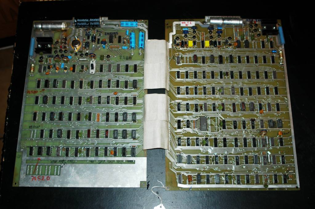
There was just one big problem. The boards are stacked on top of each other, like this:

Earlier, when I fixed the no saucer problem, I just removed the memory board and poked around on the motion board. Without the memory board the saucers (and the rocket) wouldn’t draw on the screen, but the saucer movement stuff was still working so I could debug it. In this case though I knew the thrust wouldn’t work without the horizontal and vertical velocity values generated on the memory board, but I couldn’t get to the motion board with the memory board in place!

After puzzling over this predicament for a bit, an idea presented itself: What if I unbolt the connector for the memory board and, sort of, tip it forward and then plug the memory board back into it? I messed with the rusty bolts holding the connector for a few minutes until I was able to get it unhooked. When I plugged the memory board back into the connector it hung down like this:


That gave me access to the motion board while still having the memory board in place and I was ready to attempt to figure out once and for all why the rocket wouldn’t move.

Thrust – flip flopping

The motion schematic felt cleaner, for some reason, than the memory schematic. It had four long rows of chips that, after some staring, I realized are responsible for each of the four objects in the game (saucers, saucer missile, rocket, rocket missile).


I could see where the horizontal and vertical velocity for the rocket came into the schematic, that part is clearly labeled, but what was supposed to happen next?


The output of chips F2 and F5 weren’t changing at all. Why was that? The velocities were okay, but each one was ANDed with the output of C1 and D1 at the bottom and what are those? Flip Flops. A flip flop is like a one bit memory cell (at least to this programmer…) It’s either on or off. I looked up how these are wired and the datasheet for the 7476 chip said that if the input on pin 1 was changing then the flip flop should toggle (or flip). I put the logic probe on pin 1 of chip C1 and boy was it changing. The high low and pulse lights were all flashing like crazy, but when I put the probe on the output (pin 15), I just saw a steady low signal. The flip flop was not flipping! And so it was time for another trip to Vetco, but this time they didn’t have the chip that I needed. Disaster! I ended up having to order it online and wait almost a week to find out if I had made the correct diagnosis.

Victory!

The new flip flop arrived and I installed it. I started the game and tentatively pressed on the thrust button… The ship moved! I could fly around the screen at last!

“Ted had designed additional circuitry, at Nolan’s request, to create a noise that sounded like an explosion, and more circuits to trigger the sound and other game mechanics at the right time.” – Page 40, Atari Inc. Business is Fun.

Audio Woes

Fixing thrust was a bitter sweet moment. It was sweet because I had been working on it for so long and finally got to the root cause of the problem. But I felt a strange twinge of sadness as well because I could, for the first time, see the end of the project approaching on the horizon. The game was now working 100%. The only problem left was to fix the sound. The audio circuitry occupies the upper right corner of the memory board so it’s easily accessible. It looks like this on the board:

And I even had the schematic:


How hard could this be?

Audio First Steps

Before I got too far, I wanted to make sure the TV audio was working and the game audio wasn’t. If you remember from earlier, the instructions I had followed to connect audio into the SF chassis were pretty sketchy in the sense that the description clearly had the audio wire and the ground wire swapped. I decided to test the TV audio by hooking up the audio output of a Nintendo Entertainment System (NES) to the TV audio hookup. I popped in a Tetris cartridge and hit start while I held the audio and ground wires to the audio output of the console. It didn’t sound great but I could clearly make out the familiar Tetris song, so I assumed the TV audio was okay.

Next I tried hooking the game audio to the TV but I heard nothing but noise.

Op Amps

We were getting ready to head out of town for a few days so I was a little rushed. I just poked around a bit with my multi-meter comparing voltages to shown on the schematic but nothing seemed right. The 12 volt supply voltage was okay but beyond that nothing made sense. For example the schematic says the output voltage should be 3 volts ac, or 12 volts for an explosion, but I was measuring less than half that:


Since the output at that point comes from the only integrated circuit in the entire sound system I (probably wrongly) decided that it must be to blame. I looked up the number N5741A and found out it’s something called an Op Amp, short for operational amplifier. Its job is to make things louder, I understand that. I looked up the part and supposedly Vetco had it in stock but when I arrived they couldn’t find it. They had a smaller 8 pin version but they said the pins weren’t compatible with the 14 pin version I needed. So once again I had to order online and wait the better part of a week for the chip to arrive.

The sound of silence

While waiting for the op amp I looked for something else to work on. When the game isn’t running it’s supposed to be quiet, but it wasn’t quiet at all. It sounded kind of like that noise you hear when you put a big seashell up to your ear. It sounded like the ocean. The full schematic for the game audio seemed intimidatingly complex to me at this point, but maybe I could fix one small thing at a time. Why was it noisy when it should be quiet?


Just before the audio signal was to go out to the TV it passed by a transistor connected to a wire called “Audio Gate (+ = off)”. I figured out where that was on the board and put the logic probe on the audio gate wire. Sure enough it was high when the game was off and low when it was on. So when the game is off the transistor Q12 should be on and shorting the audio signal to ground which should make it quiet. But it wasn’t quiet.

Maybe transistor Q12 was bad? I had an appropriate replacement from an earlier run to Vetco so I popped it in. No luck. It sounded just as bad as noisy as before. I puzzled over this for a bit before deciding to check the audio gate signal with that oscilloscope I had purchased earlier but barely used. Maybe more was going on than I could detect with the logic probe?

Sure enough the signal that looked solidly high or low on the logic probe looked like a mess on the oscilloscope. I figured that noise was rapidly opening and closing the transistor when it should be solidly open and that was why I was hearing noise on the output. But where was the noise coming from? The audio gate signal was coming directly from the third board in the stack, the Sync-Star board, so I pulled the first two boards out and ran with just that board. I poked around trying to figure out what was going on, but everywhere I looked I saw noise. What appeared to be clean digital signals on the logic probe were a mess on the oscilloscope. But where was all that noise coming from?

Timer Part 2

While trying to figure out why the signal into Q12 was so noisy, I found myself looking at the Sync-Star board. The only way I know to get rid of high frequency noise is with capacitors so I was staring at the capacitors and one looked very suspicious, like the pictures of bad electrolytic capacitors I’d seen online. It clearly connected into the timer circuit. How did I miss this before? It’s outlined in blue below:


I yanked it out and hooked it up to my capacitor meter. It read almost 0 when it was supposed to be 5 microfarads. No wonder my timer was running too fast. I put a new 5mfd cap in and put back the original 100K pot (removing the 500k one I had kludged in earlier) and the timer started working exactly like it should. I had finally fixed the real problem with the timer and it was exactly what Seamus had told me it would be.

Op Amp Part 2

Meanwhile my new op amp arrived and I eagerly desoldered the old one, soldered in a new socket and popped in the new chip. It looked like this:

But nothing changed. I got the exact same readings I had with the old chip. Maybe fixing the sound wasn’t going to be so easy after all?

Simplify

At this point I really wasn’t sure what to do. If the op amp wasn’t bad, what was? And how would I find it among the complicated maze of resistors, capacitors and transistors? I stared at the schematic in dismay until finally I noticed something. It looked like the op amp had two inputs. Sure enough, when I googled “op amp” I found images like this:


So the op amp has a “non-inverting” or + input and an inverting or – input. Now looking at the whole schematic I could see that most of it fed into the non-inverting input (outlined in red below), but a relatively small and simple section (outlined in green) fed into the inverting input.


Maybe I could temporarily disable the big red section and just get the little green section (that is clearly marked on the schematic as “missile sounds” and “turn sounds”) working and then tackle the much bigger and more complicated part? But could I run an op amp only with only the inverting input? Again, the internet said, “sure, why not?” with images like this:


That looks almost exactly the circuit I’m dealing with and seems to say that as long as I connect the + side of the op amp to ground I can send my signal in the “-” side and it should work just fine.

So I unsoldered one end of the capacitor that connected the entire “red” section and also a resistor and then shorted the + pin on the op amp to ground so that I only had the small green section feeding into the amp AND… nothing happened. I still didn’t hear any sound at all.

False Optimism

“Okay, so maybe that’s good”, I thought. “If it doesn’t work with just the green section then the red section might be fine. Maybe I’ve narrowed the problem down to this little green section and it’s so small that it’s going to be simple to debug. There just aren’t that many things going on here. Either the input signals are bad, or one of the resistors is bad (unlikely) or a wire trace is broken on the circuit board, or there’s a short, or some such. It should be obvious in no time.” And so I set out to track the problem down.

A Long Project

At this point in the story I should note that I had been working on this (part time) for a month and a half. When I say stuff like “and then I thought”… what that really means is I tried ten other stupid things, sometimes over several days, until I finally had a decent thought about how to move forward. With that note, I return to the story…

Testing Testing

I measured the resistors. They all matched the values shown on the schematic. I measured capacitor, it was fine. I made sure the traces were okay and that I had continuity between all the points that should be connected. Everything looked perfectly fine.

I got out the oscilloscope and watched the signals coming in for missile sounds. They looked good. I watched the signal for turn sounds. Turning one direction made a nice even square wave but turning the other direction the square wave looked much more feeble. All the signals were noisy.

If I pulled out the op amp the signal looked okay. If I put in the op amp the signal went away as if it had been overpowered in some way.

I spent days like this. Testing and retesting. Seeing a few strange things: the noise, the funny square wave, but none of it made any sense.

Desperation

Once I had checked and rechecked everything several times, I was back where I started, wondering about the op amp. Maybe the new one was bad too? I looked up the pin outs on the 8 pin version of the op amp, the one they had at Vetco that the guy behind the counter said wouldn’t work and I realized that it would work. I just had to put it in the right place in the socket to line up the pins with the 14 pin version. And so, I made the drive to Vetco once again and bought two of their 8 pin op amps. When I got home I pulled the 14 pin op amp out of the socket, plugged the 8 pin version in in the right place AND… still no sound.

Recapping

Whenever I was completely out of ideas I would replace a few of the electrolytic capacitors in the part of the audio section I had disabled. These capacitors are infamous for going bad over time so it wouldn’t hurt for me to replace them with fresh ones (as long as I got the polarity of their leads correct when I put the new ones in). I always tested them as I took them out and although they were always out of spec they were never wildly off, at least not yet…

A Lucky Guess

Frustrated by my slow progress on the audio, I decided to look into something fishy I had noticed earlier: When I pushed one of the rotate buttons I got a nice square wave feeding into the sound circuit, but when I pushed the other one the square wave was incredibly noisy. Where was the noise coming from? I tracked it back to right where the buttons on the control panel come in to the memory board. The two buttons come in at the places I marked red and green below:


If I put my meter on the red contact I would get (about) 0 volts and if I pushed the button I would get 5 volts. Great. But If I did the same thing on the green button, instead of 5 volts I would get about 1.8. Why so low? I suspected another chip was bad. Not bad enough to stop working since the rocket was rotating fine in both directions when I played the game, but enough to create the noise problem I was hunting. But which chip is bad, E5 or E6? If I had taken a minute to think about it I would have seen that it was probably E5 because both buttons connect to E6 and one of the buttons is working fine. Instead I just looked at the bad button and said to myself, “well it’s connected to two chips, either of which could be bad. One is a 7402, which I don’t have sitting here on my desk, and one is a 7400 which I happen to have right here…” So I yanked the 7400 (E5) and put in a new one and the problem was solved.

Still Stuck

But even with my square waves looking the same while turning both directions, the sound still didn’t work. I didn’t expect this to fix the sound after all, just to make the signal look the same. So that was one mystery solved but the other mystery was still out there: why were all my signals so noisy? When the rotate signal came into the “green” section of the audio chips, it immediately went through a 47K ohm resistor. That caused the voltage to drop greatly which made the signal much smaller relative to the noise I was seeing. Maybe there was more noise than signal and that’s why I didn’t hear anything recognizable?

Sweet Dreams

Sometimes when I’m stuck on a hard problem I think about it at night before I go to sleep, and sometimes I dream about the problem, and sometimes those dreams are actually helpful. I had dreamt about the audio several times, more like nightmares really, and so far it hadn’t been any help in tracking down the problems I had been having, but one morning I woke up with a clear thought in my head: The Power Supply. I had installed that new switching power supply at the beginning of the project. Could that be the source of all the noise? I hadn’t seriously considered that before because, well, that part was new and new stuff is always better right?

Sure enough when I put the oscilloscope directly across the power supply I saw the same noise I was seeing throughout the game. I disconnected the switching supply and reconnected the old bad power supply. It wasn’t strong enough to drive the display properly but it was much less noisy. I should have taken Seamus’s original advice and rebuilt the old power supply.

Power Supply Part 2

So I took the old supply off the machine and started to take it apart. It was in pretty bad shape. The transformer was completely rusty and something was oozing out of the end of the big 10,000mfd capacitor. It looked like this:


I started to disassemble it with the intent to replace all the obviously bad parts. I had a schematic for it but it didn’t have a lot of details, for example, what transformer do I need to replace the rusty one? I tried searching online for the name of the power supply, OLV15-5, and something funny happened: Google came up with some ebay links that looked very much like what I was looking for. The manufacturer name was Elpac, not Elexon, but other than that they looked virtually identical. Even better, there was one for sale that was apparently unused, in the original packaging, for only $40. I ordered it immediately and about a week later it arrived. It looks like this:


Here’s a picture of the other side of the old and the new supplies (the old one is disassembled):


I put the new supply in and it worked great right out of the box. I no longer had random noise throughout the system. The signal through transistor Q12 was nice and quiet which made the game quiet when it wasn’t running BUT… when the game was running there was still just noise, no game sounds.

Running Out Of Time!

On Monday, I realized that I was out of time. I had worked on this project since the beginning of December and it was now February 9th. We were leaving on Sunday for a week long vacation and when we returned I was hosting three days of meetings in the same room I had been working out of, so I had to have everything cleaned up and put away by Friday. I had to get the audio working this week but I had no idea how I was going to do it. I decided on a crazy plan: The idea of getting just a small part of the audio working first had been a complete failure so what if I took the opposite approach? I would finish replacing all the electrolytic capacitors, and then hook it all back up and see what happens.

I was already more than halfway through the caps so it didn’t take long, maybe an hour, for me to complete the task. As I replaced the final capacitors I discovered one that was completely bad, just like the one that I had eventually replaced to fix the timer circuit. Here it is reading zero on my meter:


Once the caps were replaced I soldered back in the capacitor and resistor I had removed to isolate the “red” part of the audio section that fed into the non-inverting part of the op amp and fired everything up and I heard… nothing but noise.

Whit’s End

“Arrgh!!” I had been at this for weeks and it still didn’t work! What the heck was going on? For the nth time I hooked the oscilloscope up to the audio output and I saw nothing interesting on the scope. With nothing better to try I left the scope connected to the audio out from the game but disconnected it from the TV. “What’s this?” All of a sudden I was seeing a pattern on the scope that looked like an audio signal. It looked like this:

I was excited but I wasn’t ready to believe what I was seeing. I needed to hear it to know if it was true. I pulled out a set of iPhone headphones and carefully laid the audio wire and ground on to the correct parts of the plug and there it was… The beautiful sounds of Computer Space. It sounded like this:

https://www.youtube.com/watch?v=o019DYaSxUQ

It didn’t just sound good, it sounded perfect. The rotation sound was there. The missile sound was there. The thrust sound was there and when a ship blew up the deep rumbling boom was there just as it should be.

WTF?

So what was up? How broken was sound to begin with and how much was a problem with the TV I had built at the beginning of this story? I simply don’t know. Maybe some Computer Space expert will read this and let me know what I did wrong. All I know is that I followed somewhat sketchy instructions from the internet on how to connect the game to a GE SF chassis, that those instructions were clearly wrong at one point, mislabeling the audio input and ground wire. That I had tested that I could send an audio signal into the TV and hear it when I hooked it up to my NES, but that it doesn’t work with the audio signal from my Computer Space.

I pulled the board from the TV and verified that I had soldered to the right points. I compared it to the images on the internet. Then I pulled the old rusty board I had saved from the original TV. It’s a little different (S3 chassis) but I noticed that in addition to the wires being connected to it for audio, ground, and video, it looked like there was a resistor added between the audio input and ground. Could that have something to do with it? Maybe I didn’t cut enough wires from the tuner to the main board and an audio signal from the tuner was overpowering the signal from the game? I had many theories but no time to find out if any were true.

A Final Kludge

But I knew I had a good audio signal coming from the game as long as I didn’t connect it to the TV and all I needed was to amplify that signal and send it to the speaker on the back of the cabinet. That was a clear and easy thing to do, as long as you don’t mind sacrificing a small amount of authenticity. At this point I didn’t have time to be picky.

I drove to Vetco and purchased a simple 1 watt amplifier kit. The kind they use to teach kids how to solder. It had a small chip and a few discrete components. It took me less than 30 minutes to solder together. Then I hooked two wires to the power supply, two wires to the audio output and ground, and a final two wires to the speaker and I was done. It sounded great. I finally had working audio for the game.


Cleanup

My project at this point had spread out across a large folding table and both sides of a ping pong table. I had chips, tools, schematics and new and used parts scattered everywhere. I took a final picture of all the parts I had replaced from the machine over the last two+ months before cleaning everything up:


I reassembled the control panel with new carriage bolts and new old stock light bulbs I had found on ebay. I wanted to be able to play the game without putting in a quarter but wasn’t sure how to do it while maintaining the original look of the game. I decided to solder a paperclip to the coin return button in the coin mechanism. The other end of the paperclip trips the micro-switch that a quarter would trip when dropped into the machine. It works pretty slick:


I also disassembled, cleaned and reassembled the previously jammed coin counter that keeps track of how many total games have been played:

Here’s the final, reassembled and fully working machine:


More To Do

Because of my rush to finish, I didn’t get to work on the physical restoration of the yellow cabinet. It needs to be cleaned and polished to return to its former glory, but that will have to wait for another day. I’m also not happy with the buttons on the control panel. One of them sticks a bit which can leave your ship spinning out of control. I really need some replacement button caps, but those are hard to come by for this machine.

“Yeah, yeah, no it’s … it absolutely … the guy is brilliant! He’s absolutely brilliant! He just happens to not be a particularly good engineer. But his imagination and his ideas and … I mean, all the ideas that came around were his ideas.” – Ted Dabney, Retro Gaming Roundup 

Reflecting

I learned so much working on this project over almost three months. At the beginning I had never tried to debug a complex digital or analog circuit. I had never desoldered and replaced a chip. I had never used an oscilloscope. Now I feel marginally competent with all of those skills. In some sense I was lucky I was working on such a relatively simple machine. What if there had been a CPU running a program across a data bus? I’d need completely different tools (maybe a logic analyzer?) and I’d have to learn different skills. Maybe that’s next? Who knows.

And what of Nolan?

Until I started this project I had always thought of Nolan Bushnell as kind of a merry huckster. Part Steve Jobs and part PT Barnum. That feeling was reinforced when I met him for the first time at a PR event for a game we were releasing from Microsoft in 2000 called “Starlancer.” Our people had arranged for him to play in a multiplayer space battle with me and game designer Chris Roberts (of Wing Commander fame). We met him and shook his hand back stage, a few minutes before we were to start the event. I told him what an honor it was to meet him. His response, no doubt meant to impress, was to immediately launch into a bawdy story about a romantic liaison between himself and a waitress in the ball pit of Chuck E. Cheese. This was the founder of the modern videogame business?

But on this project I got to see another side of Nolan: the engineer. Sure he has taken credit for more than he should, including patenting Ted Dabney’s work without crediting him, but he also, more than anyone, created this game and made it fun. He solved difficult technical challenges including how to rotate a sprite on the screen and how to make a simple AI for the enemy saucers.

For all his well-documented flaws, this project really increased my respect for Nolan Bushnell and taught me about Ted Dabney’s important role as well. I learned new engineering skills, but I also learned even more about the history of the business I’ve been involved in now for almost 35 years and the people who made it great.

An Unexpected Call

Sunday morning we had the car packed and the kids loaded up for our ski vacation. I set the alarm, locked the front door and as I walked to the car my phone rang. It was my dad. I told him about my ultimate hack to fix the audio problems. He said he thought that was a good solution. He said that maybe the audio circuit wasn’t strong enough to drive the TV amplifier or maybe there was an impedance problem (whatever that means…). Then he told me the reason he called was he wanted his Tube Tester back. He needed it because my work on the Computer Space had made him want to get his old oscilloscope working again and he suspected one of the tubes was bad. I set the tester out for him on the front step and drove away, happy that, for once, I had inspired him, rather than the other way around.

031315_2107_FixingCompu34.png
edfries
http://edfries.wordpress.com/?p=236
Extensions