The morning of April 12, 1981, 20 years to the day after Yuri Gagarin became the first person in space, the
Space Shuttle thundered into the Florida sky.
Commander Young and Pilot Crippen were at the controls as the Shuttle ascended on its first flight.
But the launch, like much of the flight, was really under the control of four computers in the avionics bays
one deck below the crew. A fifth computer stood ready to take over in case of a catastrophic computer malfunction.
These computers, Model AP-101B, were part of IBM's System/4 Pi family.
 and STS-40 (1991). Photo courtesy of RR Auction.") The Space Shuttle AP-101B computer. This unit flew on multiple flights, including STS-38 (1990) and STS-40 (1991). Photo courtesy of RR Auction.
The Space Shuttle AP-101B computer. This unit flew on multiple flights, including STS-38 (1990) and STS-40 (1991). Photo courtesy of RR Auction.
Introduced around 1967, the System/4 Pi family was a line of compact, powerful computers designed for avionics
roles.
The military used these computers in everything from the F-4 fighter and B-52 bomber to
submarine sonar systems and
the Harpoon anti-ship missile.
Other computers in the System/4 Pi family played more peaceful roles in the development of GPS and fly-by-wire flight
controls. In space, System/4 Pi computers controlled Skylab, the first American space station, as well as Spacelab, the reusable
laboratory flown by the Space Shuttle.
Despite the important roles of System/4 Pi computers, information on them is hard to obtain—Wikipedia entirely omits the CC, SP, and ML models.1
However, I received a stack of 4 Pi marketing brochures and articles, so
I can now fill in many gaps in the history of System/4 Pi.
The first generation
The IBM System/360 line of mainframes was introduced in
1964.
System/360 revolutionized the computer industry with the concept of one family of computers
for all applications: business and scientific. The name symbolized that System/360 covered
the full 360º of applications.
The 4 Pi name extended this idea to applications in the 3-dimensional world: 4π is the number of steradians making up a full sphere.
As IBM put it, "System/4 Pi also fills a sphere—the full spectrum of military computer needs—for airborne, space, or shipboard use."
Initially, the System/4 Pi family had three models:
"Model TC (tactical computer) for satellites, tactical missiles, helicopters, and other applications requiring a very small, lightweight computer; Model CP (customized processor) for real-time computing applications; and Model EP (extended performance) for applications that require real-time calculation of very large amounts of data."2
The TC Tactical Computer
The TC Tactical Computer was a general-purpose digital computer, designed for low cost and medium-range performance
(details).
The TC had a 16- or 32-bit word, but used an 8-bit bus to reduce cost.
It supported from 8 KB to 64 KB of magnetic core memory.
It has a straightforward instruction set with 54 instructions in total, including multiply and divide.
As was common at the time, it didn't have a stack for subroutine calls, but had a branch-and-store instruction instead.
The original model ran 48,500 instructions per second.
While this is appallingly slow by modern standards, it was mainframe-level performance at the time,
comparable to a mid-range IBM 360/40 mainframe.
 The arithmetic and control subassembly of a TC computer, configured for a tactical missile. From Electronics, March 6, 1967. Also see Electronics, Oct. 31, 1966.
The TC was originally packaged in a briefcase-sized box (9.75" × 17.12" × 4.0") (below) that weighed 17.3 pounds, but it could be repackaged for different applications.
For a tactical missile, the computer was implemented on semicircular circuit boards as shown above.
The computer was constructed from TTL (Transistor-Transistor Logic)3 flatpack integrated circuits mounted on four-layer circuit boards.
Two circuit boards made a sandwich around a metal structure that provided support and cooling; this three-layer assembly was
called a "page".
A page could hold about 300 integrated circuits, so the computer was very dense.
 The IBM 4 Pi TC system. From Technical Description of IBM System 4 Pi Computers.
TC-1 computers played a critical role in Skylab, America's first space station, which was launched in 1973.4
The orientation of Skylab needed to be precisely controlled to aim its multiple telescopes.
To avoid consuming propellant, Skylab was rotated by changing the speed of three massive gyroscopes,
155 pounds each.
Two TC-1 computers controlled these gyroscopes, with one computer
active and one computer as a backup.
Each 16-bit computer had 16K words of storage that could be reloaded from magnetic tape or radio,
and executed 60,000 operations per second.
Each Skylab computer occupied 2.2 cubic feet (much larger than the briefcase-sized TC) and weighed 97.5 pounds.
The Skylab computers are notable as the first fully digital control system on a crewed spacecraft.
The TC-2 model (below) was much faster (125,000 operations per second) and weighed 80 pounds.
It was used for Navigation/Weapons Delivery in the A-7D/E attack fighter. In 1976, it was upgraded to the TC-2A, which was still faster (454,000 operations per second), supported more memory, and added 12 more instructions.
 computer.
Photo courtesy of Alex1970-14;
this computer is currently on eBay if you want it.") A TC-2 computer, specifically the Test Set Control Computer CP-993/ASM. It looks the same as the A-7 aircraft's CP-952/ASN-91(V) computer.
Photo courtesy of Alex1970-14;
this computer is currently on eBay if you want it.
A TC-2 computer, specifically the Test Set Control Computer CP-993/ASM. It looks the same as the A-7 aircraft's CP-952/ASN-91(V) computer.
Photo courtesy of Alex1970-14;
this computer is currently on eBay if you want it.
Like most computers in its era, the TC used magnetic core memory; each bit was stored in a tiny toroidal core of lithium nickel ferrite, strung onto a grid.5
The core planes in the TC and other first-generation 4 Pi computers were about 6 inches on a side.
With 16,384 cores in a plane, each plane held 16 Kbits.
Thus, the 8-kilobyte memory in the TC required a stack of four core planes.
A significant advantage of core memory was that, because it was magnetic, the data was preserved even when the memory was not powered. It was also highly resistant to radiation.
 core memory plane is the commercial version of the planes in the first-generation System/4 Pi computers.
Photo by José Luis Briz Velasco, CC BY-SA 4.0, cropped.") This (somewhat damaged) core memory plane is the commercial version of the planes in the first-generation System/4 Pi computers.
Photo by José Luis Briz Velasco, CC BY-SA 4.0, cropped.
This (somewhat damaged) core memory plane is the commercial version of the planes in the first-generation System/4 Pi computers.
Photo by José Luis Briz Velasco, CC BY-SA 4.0, cropped.
The CP Customized Processor
One step up from the TC series was the CP Customized Processor (briefly called Cost Performance).6
It used a 16-bit CPU, but had a wide 36-bit bus to memory for higher performance (including two parity bits and two storage protection 7 bits).
Unlike the TC series, the CP series was (optionally) microcoded internally, so the instruction set could be easily customized.8
The CP system had completely different instruction formats from the TC system.10
The base model had 36 instructions and executed 91,000 instructions per second.
The CP supported multiple addressing modes, more advanced than the simple addressing of the TC system.
While the TC ran at 330 kHz, the CP ran at 2.4 megahertz. The CP's performance didn't improve
as much as the faster clock would suggest, since both systems used slow core memory.
 The IBM CP computer. from "IBM System/4 Pi Model CP" brochure, 1967.
One of the strengths of System/4 Pi was input/output, allowing it to communicate with external devices in real time.
The CP-1 had extensive I/O capabilities: three high-speed parallel inputs, a high-speed parallel output, a serial output, 24 discrete input lines,
144 discrete output lines, and 24 interrupt lines.
To support all these I/O signals, the CP-1 was packaged in two boxes: one for the computer itself, and one for the I/O interface.
The CPU box is shown below; the I/O coupler box was similar, but the front sported over a dozen connectors for I/O lines.
The CP-1 was used in the navigation/threat analysis system in the EA-6B Prowler electronic-warfare aircraft.9
 The CP-1 computer, designated the CP-926/AYA-6. From "IBM System/4 Pi and Advanced System/4 Pi Computers" brochure, August 1973.
The CP-2 was the navigation/weapons delivery computer in the F-111 fighter plane, integrating radar and weapons.
It was faster than the CP-1, perhaps because it was not microprogrammed, executing 150,000 instructions per second.
It was also smaller, occupying one 47-pound box, although it had less I/O support.
Unfortunately, this F-111 computer was said to be a disaster operationally because the
computer had reliability problems and limited performance.
The CP-2 was later replaced by the enhanced CP-2EX.
 The CP-2 computer, designated the AN/AYK-6. The three-digit dial on the front was covered and fastened with security wire before use, so it must have been important. The core memory stack is in the middle of the computer, with 8K to 16K words of storage. The circuit pages are in front. Photo from an IBM Thread, which also shows a disassembled TC-2 computer.
The CP-3 computer (below) was used for navigation and weapons delivery in the A-6E Intruder (1970) and other aircraft, replacing an earlier Litton computer with an unreliable drum memory.
This computer could be integrated with laser-guided "smart" bombs.
It was similar to the CP-2 and had the same performance, but had different I/O functions.
 The CP-3 computer, designated the CP-985/ASQ-133. From "IBM System/4 Pi and Advanced System/4 Pi Computers" brochure, August 1973.
Like the TC, the CP was constructed from flat-pack TTL chips mounted on circuit boards called "pages".
However, the CP used smaller pages with six layers instead of four; each double-sided page could hold up to 156 integrated circuits.
Each page had two 98-pin connectors, reusing the style of connector that IBM used in Apollo for the
Saturn V rocket's Launch Vehicle Digital Computer (LVDC).
IBM standardized on this type of page for decades; the page below was used in the AWACS computer (1991) and is almost identical to
the pages in the CP computer in 1967.
 A standard IBM System/4 Pi page assembly. From "AWACS Data Processing Subsystem" brochure, 1991.
The EP (Extended Performance) computer
The EP was the most powerful of the original System/4 Pi computers.
It was a 32-bit computer compatible with IBM System/360 mainframes, specifically the 360 Model 44.11
For input/output, the EP used the same I/O channel architecture as the System/360 mainframes.
To support the complicated 360 instruction set, the EP was microcoded.
It executed 190,000 instructions per second and weighed 75 pounds.
Floating-point support was available as an option.
 A mockup of the EP computer. The core memory is the dark box in the in the upper right, From Technical Description of IBM System 4 Pi Computers.
A multiprocessor version of EP, the EP/MP, supported up to three CPUs sharing memory.
It was delivered for the Air Force's Manned Orbiting Laboratory (MOL), but the MOL
project was canceled (details).
The multiprocessor system was also used for the VS ANEW anti-submarine research project, part of the VSX program
that led to the Lockheed S-3 Viking, an aircraft that used the System/4 Pi SP-0A computer instead of the EP.
The next generation: Advanced System/4 Pi
Early in 1970, IBM created the Advanced System/4 Pi family.12
These 32-bit systems were significantly faster, smaller, and more advanced than the previous System/4 Pi computers.
These computers took advantage of improved integrated circuits, called Medium-Scale Integration (MSI).
These integrated circuits held 10 to 100 gates per chip, compared to the earlier
Small-Scale Integration (SSI) chips with 1 to 10 gates per chip, allowing a chip to implement a more complex
function, such as a shift register, counter, or adder.)
Moreover, these computers used faster core memory, reducing the memory cycle time from 2.5 µs to 1 µs.
This series originally consisted of three lines: Advanced Processor (AP),
Subsystem Processor (SP), and
Command and Control (CC).
The AP line is the largest and most famous, powering the Space Shuttle as well as numerous aircraft.
A few years later, IBM introduced the ML line.
Although the SP, CC, and ML lines are obscure, they have
some interesting features.
Advanced Processor (AP)
For the most part, the AP computers used an instruction set and architecture that was derived from the System/360,
called MMP (Multipurpose Midline Processor).13
Unlike the EP computers, the
AP computers were incompatible with System/360: the instruction format, the registers, the addressing modes,
and the condition codes were different.
Some AP computers used a 16-bit instruction set that was an Air Force Standard, called MIL-STD-1750A.
The Advanced Processor line started with the AP-1, a 32-bit processor that performed 450,000 instructions per second and weighed 36 pounds.
It could be programmed in assembler or the military's JOVIAL language.
It supported 16K halfwords to 64K halfwords of storage internally, and more could be added in an external box.
It had four high-speed I/O channels, handling up to 15 devices per channel.
Floating point was available as an option.
The AP-1 is described in detail here.
 The AP-1 computer, designated CP-1075/AYK. From "IBM System/4 Pi and Advanced System/4 Pi Computers" brochure, August 1973.
The AP-1 computer was used in the F-15 fighter for navigation/weapon delivery and data management.
It was also used by Japan in the F-4 fighter.
An upgraded computer, the AP-1R, had 256K of core memory and performed over 1 million instructions per second; it was used in the F-15E aircraft in 1983.
The AP-1A was used in the development of the AWACS Seek Bus tactical communication system and the
Joint Tactical Information Distribution System (JTIDS).
The AP-2 computer was almost identical to the AP-1 in appearance and functionality, with some changes to its I/O capabilities.
It was used in the Central Integrated Test System (CITS) on the B-1 bomber to provide real-time testing and troubleshooting
(details).
The AP-101 computer expanded the AP-1's instruction set from 83 instructions to 151, as well as having slightly faster core memory.
The first nine AP-101 computers were used in NASA's digital fly-by-wire research program that used the F-8 fighter (link).
The AP-101 was also used for GPS development.
 The AP-101 computer. From "IBM System/4 Pi and Advanced System/4 Pi Computers" brochure, August 1973.
Around 1975, the AP-101B computer was developed for the Space Shuttle.14
The first step was improving the instruction set to support "high order languages" better, resulting in the AP-101A.
Next, double-density core memory was used, creating the AP-101B that the Space Shuttle used for many years.
The AP-101B computer was partnered with the IOP (I/O Processor), essentially a second computer that handled I/O, providing 24 data buses to the rest of the Space Shuttle.
For reliability, the Space Shuttle had four redundant AP-101B computers that ran in parallel and
voted on each output, so a faulty computer could be excluded.
Moreover, a fifth computer was ready as a backup, using independently programmed software in case a
software fault caused all four primary computers to fail.15
 and AP-101B computer (right). Photo courtesy of RR Auction.") The Space Shuttle I/O Processor (IOP, left) and AP-101B computer (right). Photo courtesy of RR Auction.
The Space Shuttle I/O Processor (IOP, left) and AP-101B computer (right). Photo courtesy of RR Auction.
The Space Shuttle computer had 104K 32-bit words of memory.
The AP-101B held ten memory pages (i.e., circuit boards), each holding 16K×18 bits, while the IOP held six pages, each holding 8K×18 bits.16
Although the memory was physically split between the two boxes, it acted as a unified shared memory.
 module stores 8K by 18 bits (details). This is a lower-capacity page, either from the IOP or from an early version of the AP-101. The page unfolds, with the core planes inside. Photo from klabs.") The Space Shuttle's EP/MCM (Extended Performance/Modular Core Memory) module stores 8K by 18 bits (details). This is a lower-capacity page, either from the IOP or from an early version of the AP-101. The page unfolds, with the core planes inside. Photo from klabs.
The Space Shuttle's EP/MCM (Extended Performance/Modular Core Memory) module stores 8K by 18 bits (details). This is a lower-capacity page, either from the IOP or from an early version of the AP-101. The page unfolds, with the core planes inside. Photo from klabs.
The AP-101C computer (1977) had multiple improvements: quadruple-density modular core memory, upgraded logic technology,
and repackaging to reduce cost.17
The AP-101C had 32K words of storage and ran at over 500,000 operations per second.18
The AP-101C was used in the B-52D Digital Bombing and Navigation System.
It was also installed in the B-52G/H bomber as part of the Offensive Avionics System.
The AP-101C was designed to survive radiation and electromagnetic pulse (EMP) hazards, with radiation-hardened circuits and
parity in memory.
Its "nuclear circumvention" feature resumed operation 50 milliseconds after a nuclear event,
probably detecting a nuclear blast and quickly rebooting to avoid harmful effects such as latchup.
 The AP-101C computer. From "IBM Model AP-101C" brochure, September 1978, retouched.
The AP-101C started the Modular Computer Series,19 which used 9"×6.4" pages, much larger than the previous pages.
The MCS pages were modularized, supporting standard modules for CPU, memory, timing, power supply, testing, and a
new military serial bus called MIL-STD-1553A.
While previous computers were customized by changing the microcode in core-based Read Only Store (ROS), the AP-101C could be customized
by changing PROMs (Programmable Read-Only Memories) and PLAs (Programmable Logic Arrays).
 page assembly. This page is from an AWACS computer, From \"AWACS Data Processing Subsystem\" brochure, 1991.") A Modular Computer Series (MCS) page assembly. This page is from an AWACS computer, From "AWACS Data Processing Subsystem" brochure, 1991.
A Modular Computer Series (MCS) page assembly. This page is from an AWACS computer, From "AWACS Data Processing Subsystem" brochure, 1991.
In the mid-1970s, the Air Force realized that the cost of developing software for complex military systems was a problem,
partially because different computers had incompatible instruction sets.
To solve this problem, the Air Force developed a standard 16-bit architecture and instruction set,
releasing a standard called MIL-STD-1750A in July 1980.
The Air Force made 1750A mandatory for future projects (unless there was a compelling reason not to use it), so
many companies implemented computers that were compatible with 1750A.
IBM developed a version of the AP-101 that ran the 1750A instruction set and called it the AP-101E.
The AP-101F (1982) was innovative in several ways.
It was a dual-architecture computer that could support both the existing AP-101
instruction set (MMP) and the 1750A standard instruction set, providing a low-risk upgrade path.
It was much faster, using a pipelined architecture that ran over 1 million instructions per second (MIPS).
The AP-101F also used DRAM (Dynamic RAM) semiconductor memory, which was faster, denser, and used less power than core memory.20
Choosing semiconductor memory over core memory may seem like an obvious choice, but
magnetic core memory had two significant advantages.
First, core memory is nonvolatile: it keeps its contents when the power is off, so programs don't need to be loaded at boot.
Second, core memory is resistant to nuclear radiation and cosmic rays, dangers that can easily flip bits in semiconductor memory.
The volatility problem was solved by providing battery backup for the semiconductor memory.
The AP-101F solved the radiation problem by using semiconductor memory backed up by "shadow" core memory.
Later computers used semiconductor memory with error-correcting codes that could recover from flipped bits:
each 16-bit word in memory had 6 additional bits for error correction.21
Because of the tradeoffs, some computers (such as the ML-1 discussed below) could use either core memory or semiconductor memory, depending on the application.
The B-1B bomber used eight AP-101F computers: one each for guidance and navigation, weapons delivery, controls and displays, critical task redundancy, preprocessor, and system test (CITS), while two computers provided terrain following
(see Standards Application to B-1B Avionics Program).
To minimize schedule risk, the B-1B initially used the AP-101C from the B-52, then transitioned to the AP-101D.
Because of the need for a more powerful processor and pressure to use the standard 1750A instruction set, the B-1B moved to the
dual-architecture AP-101F, gradually rewriting software from assembly to the standard JOVIAL language.
Shuttle redesign: the AP-101S
The most unrelenting enemy of a military computer is Moore's Law.
Even if you start with a cutting-edge computer, it can take a decade for an aircraft to enter service, and then the plane may
be flown for decades. Meanwhile, commercial computers become more than an order of magnitude more powerful every decade.
The result is that military computers are constantly fighting obsolescence.
Space computers have the same problem:
the Shuttle's AP-101 computer was developed in 1972 but the Shuttle didn't fly until 1981, making the Shuttle computers obsolete
from the start.
To improve performance, IBM started redesigning the computer the next year, creating the AP-101S.
It executed 1.27 million instructions per second (MIPS), three times as fast as the AP-101B.
However, this performance increase was nothing compared to the improvements in microprocessors.
In 1991, when the AP-101S first flew, a Motorola 68040 microprocessor executed 44 MIPS, leaving the AP-101S in the dust.
By the time the Shuttle program ended in 2011, an Intel Core i7 processor provided a blistering 100,000 MIPS.
Astronauts had to use laptops to
make up for the lack of computational power in the main computers; one flight carried 18 Thinkpad laptops.
 The AP-101S with its cover removed. This is a prototype; the green boards on the left are likely development boards instead of the I/O boards that are normally in these positions.
Despite its lack of absolute performance, the AP-101S was a substantial improvement over the earlier Shuttle computer.
The AP-101S fit the functionality of the AP-101B computer and the IOP (I/O Processor) into one box instead of two,
saving 60 pounds. With five computers on the Shuttle, this change freed up 300 pounds for payload.
As well as tripling the speed, the AP-101S was more reliable, had 256K words of memory instead of 104K,
and used 100 watts less of the Shuttle's limited power.
The AP-101S remained plug-compatible with the old computer and could run the same software, making upgrading
straightforward.
 for the 36-bit \"fraction\" ALU. Much of the logic uses FAST (Fairchild Advanced Schottky Technology) TTL chips for improved performance. The board is covered with brown conformal coating to protect it from the environment. Click this image (or any other) for a larger version.") One of the CPU boards from the AP-101S, specifically the CPU1 board. If you look closely, you can see "bodge wires" that correct errors on the board. The nine large ICs in the center are four-bit arithmetic-logic unit chips (74F181) for the 36-bit "fraction" ALU. Much of the logic uses FAST (Fairchild Advanced Schottky Technology) TTL chips for improved performance. The board is covered with brown conformal coating to protect it from the environment. Click this image (or any other) for a larger version.
One of the CPU boards from the AP-101S, specifically the CPU1 board. If you look closely, you can see "bodge wires" that correct errors on the board. The nine large ICs in the center are four-bit arithmetic-logic unit chips (74F181) for the 36-bit "fraction" ALU. Much of the logic uses FAST (Fairchild Advanced Schottky Technology) TTL chips for improved performance. The board is covered with brown conformal coating to protect it from the environment. Click this image (or any other) for a larger version.
Like the previous processors, the CPU of the AP-101S was constructed from multiple pages of TTL chips.
Unlike the earlier AP-101B, the AP-101S used large "MCS" pages, as shown above.
The diagram below illustrates how the upgraded AP-101S computer was formed by combining the pipelined CPU22 from the high-performance AP-101F,
the I/O Processor from the original Shuttle computer, and the semiconductor memory from the AP-102 (discussed in the next section).23
 for a larger version.) From \"A New Computer for the Space Shuttle: The AP-101S General Purpose Computer (GPC) Upgrade\", IBM Technical Directions, 1986.") The upgrade path for the Space Shuttle computer. (Click this image (or any other) for a larger version.) From "A New Computer for the Space Shuttle: The AP-101S General Purpose Computer (GPC) Upgrade", IBM Technical Directions, 1986.
The upgrade path for the Space Shuttle computer. (Click this image (or any other) for a larger version.) From "A New Computer for the Space Shuttle: The AP-101S General Purpose Computer (GPC) Upgrade", IBM Technical Directions, 1986.
The Shuttle could carry a space laboratory called Spacelab (completely different from Skylab) in the cargo bay to provide a spacious research environment.
Spacelab had independent computers from the Space Shuttle, originally French-built CIMSA 125 MS computers.24
In 1991, these Spacelab computers were
replaced with IBM AP-101SL computers.25
The AP-101SL was compatible with the 16-bit CIMSA computer, so it could run "Experiment Computer Operating System" and other Spacelab software without change.
 An AP-101SL computer at the National Air and Space Museum, VA. The slot at the top held nickel-cadmium batteries to preserve the contents of the CMOS memory, but the batteries were removed for safety during storage.
Photo by Sanjay Acharya, CC BY-SA 4.0, cropped.
An AP-101SL computer at the National Air and Space Museum, VA. The slot at the top held nickel-cadmium batteries to preserve the contents of the CMOS memory, but the batteries were removed for safety during storage.
Photo by Sanjay Acharya, CC BY-SA 4.0, cropped.
Internally, the Spacelab AP-101SL computer is very similar to the Shuttle's AP-101S. It has fewer boards than the AP-101S, since
it doesn't include the Shuttle's IOP (I/O Processor).
The processor boards, the semiconductor memory,26 and the power supplies are nearly identical
to the Shuttle computer, while the I/O boards are different.27
 The AP-101SL with the cover removed. Photo courtesy of Kyle Owen.
AP-102 and VHSIC
Going back to the mid-1980s, IBM introduced the AP-102 computer.
By 1992, it had become the most popular of IBM's avionics processors, with 1000 units sold.
The AP-102 was a technological jump compared to the AP-101 since it used two VLSI (Very Large Scale Integration) chips, each containing 12,000
gates: one chip implemented the Instruction Processing Unit and the other chip implemented the Extended Arithmetic Unit (fixed
and floating-point multiplies and divides).
These chips were implemented with 2 µm NMOS technology.
The AP-102 used CMOS static RAM for storage, which was much denser than core memory and used a tenth of the power.
Because CMOS RAM loses its contents without electricity, the AP-102 used battery backup, lithium thionyl chloride cells that
could power memory for up to seven years.
.") The AP-102 computer. From IBM Technical Directions, 1985 (cover).
The AP-102 computer. From IBM Technical Directions, 1985 (cover).
The AP-102 was compact, half the width of an AP-101.28
It weighed 20.8 pounds and used 95 watts.
It ran the Air Force's standard 1750A instruction set, executing over 1 million instructions per second.
The AP-102 was used in many aircraft in the late 1980s, including the stealth F-117A Nighthawk fighter, the MH-53J Special Operations helicopter,
the F-4's Navigation & Weapon Delivery System (AN/ASQ-203),
an "unspecified gunship", and a classified application.
A few years later, the AP-102 was upgraded with a new technology called VHSIC.
If you've programmed an FPGA (Field-Programmable Gate Array), you've probably used the Verilog or VHDL languages.
VHDL turns out to be a nested acronym, standing for VHSIC Hardware Description Language, where VHSIC stands for Very High Speed
Integrated Circuit. But why this strange name?
In 1980, the Department of Defense started a billion-dollar program to help the US military keep its technological lead over
the Soviet Union.
This program, the Very High Speed Integrated Circuit program, was intended to get advanced, state-of-the-art
integrated circuits into military usage faster.
IBM was one of the contractors that developed these VHSIC "superchips."
IBM created the V1750 processor, a radiation-hardened chip that ran the standardized Air Force instruction set, 1750A.29
This CMOS chip was built with 1 µm features, advanced for the time, and ran at 3 MIPS (million instructions per second).
The AP-102 mission computer was upgraded around 1992 to use the V1750 processor,
resulting in the AP-102A.
With the V1750 processor, IBM fit the CPU and memory onto a single card, a drop-in replacement for six cards in the
existing AP-102.
The result was up to 16 times as much memory and a factor of 3 improvement in performance, along with improvements in reliability,
weight, and power consumption.
Subsystem Processor (SP)
The next member of the Advanced System line is the SP Subsystem Processor,
intended to be a subsystem in a larger system.
Compared to the AP series, the SP computers have a 16-bit word instead of a 32-bit word, and are generally smaller and slower
but use less power.
The SP computers are architecturally simpler, with just two or three registers.
On the Space Shuttle, the astronauts received flight and control information through four screens
30
These monochrome green CRTs displayed text and primitive graphics using vectors—lines drawn on the CRT—rather than pixels.
Each screen was controlled by a Display Electronics Unit (DEU).
 The left screen shows the
Universal Pointing attitude display.
The right screen shows the Relative Navigation screen for rendezvous operations.
At the bottom of the photo are the two grid-style keyboards for communication with the computer, with the CRT controls in between.
Two laptops are sitting on top of the console. Mission Pilot Kevin Chilton is in the pilot's seat. From National Archives.") Three of the Shuttle's CRT displays. (Click for a larger image.) The left screen shows the
Universal Pointing attitude display.
The right screen shows the Relative Navigation screen for rendezvous operations.
At the bottom of the photo are the two grid-style keyboards for communication with the computer, with the CRT controls in between.
Two laptops are sitting on top of the console. Mission Pilot Kevin Chilton is in the pilot's seat. From National Archives.
Three of the Shuttle's CRT displays. (Click for a larger image.) The left screen shows the
Universal Pointing attitude display.
The right screen shows the Relative Navigation screen for rendezvous operations.
At the bottom of the photo are the two grid-style keyboards for communication with the computer, with the CRT controls in between.
Two laptops are sitting on top of the console. Mission Pilot Kevin Chilton is in the pilot's seat. From National Archives.
Internally, the DEU looks very much like the Shuttle's AP-101B computer, a large box filled with squat pages.
One of the pages is the CPU of an SP-0 computer, while other pages provided 32K words of memory, interfaced to the main computers,
and drove the CRT.
The SP-0 handled filtering of keyboard data, time maintenance, and health monitoring.
The SP-0 received dynamic data from the Shuttle's main computers and formatted the data for the CRT display.
. This is an engineering prototype. Photo courtesy of RR Auction.") The Space Shuttle Display Electronics Unit (DEU). This is an engineering prototype. Photo courtesy of RR Auction.
The Space Shuttle Display Electronics Unit (DEU). This is an engineering prototype. Photo courtesy of RR Auction.
The SP-0A computer below was used in the Lockheed S-3 Viking anti-submarine aircraft, probably
to detect enemy radar and communication signals in the AN/ALR-47 Electronic Support Measures system.
 The SP-0A computer. From "IBM System/4 Pi and Advanced System/4 Pi Computers" brochure, August 1973.
The SP-0B computer was used in the Midcourse Guidance Unit for the Harpoon anti-ship missile.31
It originally had magnetic core memory, upgraded to semiconductor memory in 1974.
Note the curved packaging for the SP-0B that helps it fit inside the missile.
 The SP-0B computer. From "IBM System/4 Pi and Advanced System/4 Pi Computers" brochure, August 1973.
The SP-1, below, had one more register than the SP-0, as well as higher performance, running 342,500 operations per second.
It was also available as the unpackaged SP-1A, weighing just 3.6 pounds.
The SP-1M added a few instructions to improve performance.
The much larger SP-1B weighed 200 pounds and was designed for ground usage.
IBM gives a long list of applications for the SP-1: "F-4 ATIS, navigation, missile and drone stabilization and control, communications processor,
torpedo stabilization and control."
 The SP-1 computer. From "IBM System/4 Pi and Advanced System/4 Pi Computers" brochure, August 1973.
The bulky SP-201 computer was an outlier from the rest of the SP series, since it weighed 660 pounds.
Its performance was higher than the other SP models, running 450,000 instructions per second.
This computer was part of the sonar system used on Los Angeles and Ohio class submarines.
The bow of the submarine contained a giant sphere, 15 feet in diameter, studded with over a thousand transducers to detect underwater sounds.
The SP-201 was a "post-classification signal processor"32 in the AN/BQQ-5, analyzing
these sonar signals and driving
scrolling "waterfall" displays with green lines indicating the presence of ships (or sometimes whales).
This computer was carefully designed to be lowered through a submarine's standard 25-inch hatch.
 The SP-201 computer, designated CP-1125/BQQ-5. From "IBM System/4 Pi and Advanced System/4 Pi Computers" brochure, August 1973.
Command and Control (CC)
Although the AP series was the star of the Advanced System/4 Pi line, massive CC computers ran the
Boeing E-3A Sentry AWACS (Airborne Warning and Control System) aircraft.
The AWACS is a Boeing 707 with a rotating 30-foot radar dome on top, appearing as if a giant mushroom sprouted from the fuselage.
This radar tracked activity over 250 miles away, providing a comprehensive view of the battlefield.
Inside the AWACS, the CC was the central mission computer, processing radar data and sending it to 14 display terminals, as well
as providing command-and-control functions.
The CC-1 was developed in 1971 as the top performer of the System/4 Pi line at 740,000 operations per second.
It supported the System/360 architecture—including System/360 peripherals—but also supported the optimized "CC-1 architecture".33
The CC-1 was followed by the CC-2 (1980), which boosted performance to 2 million instructions per second through the use of
Super Schottky TTL.
The CC-2E computer with Memory Enhancement provided four times the main storage and eight times the bulk storage.
The CC-2E was massive compared to the rest of the 4 Pi line, weighing 1826 pounds and standing almost 6 feet tall.
It ran over 2.7 MIPS (Million Instructions Per Second), over twice the speed of the Space Shuttle's upgraded computer.
The computer was redundant to ensure reliability.
It also included "nuclear event detection and survivability".
, Computer Arithmetic Unit (CAU),
Computer Control (CC),
Monolithic Memory Unit (MMU),
and Bubble Memory Unit (BMU).
From \"AWACS Data Processing Subsystem\" brochure, 1991.") The baseline configuration for the AWACS CC-2E digital computer.
Components are Digital Multiplexer (DMX), Computer Arithmetic Unit (CAU),
Computer Control (CC),
Monolithic Memory Unit (MMU),
and Bubble Memory Unit (BMU).
From "AWACS Data Processing Subsystem" brochure, 1991.
The baseline configuration for the AWACS CC-2E digital computer.
Components are Digital Multiplexer (DMX), Computer Arithmetic Unit (CAU),
Computer Control (CC),
Monolithic Memory Unit (MMU),
and Bubble Memory Unit (BMU).
From "AWACS Data Processing Subsystem" brochure, 1991.
The photo above shows the refrigerator-sized cabinet of the CC-2E.
The computer is constructed from two types of boards:
most of the system used the large MCS pages, while
the DMX and Computer Control units used the squat pages of earlier 4 Pi systems.
The CC-2E made use of an unusual technology for mass nonvolatile storage: bubble memory.
In the 1970s, bubble memory was the storage technology of the future, providing hard disk capacity at core memory speeds.
It used tiny magnetic "bubbles" moving along tracks by magnetic fields.
However, improvements in semiconductor memory made bubble memory uncompetitive; by 1981, the New York Times snarkily referred
to The Computer Bubble that Burst.
Bubble memory was popular with the military because it was insensitive to vibrations, unlike hard disks.
Each bubble memory unit (BMU in the photo) in the CC-2E stored 8 megabytes, four times as much as a similarly-sized semiconductor-based monolithic memory unit (MMU).
These replaced four rotating magnetic drums in the original CC-1, each storing 400,000 words.
To safeguard information from falling into the wrong hands, the bubble memory modules had a "data destruct" feature.
 The Computer Arithmetic Unit Assembly, one of two in the AWACS computer. From "AWACS Data Processing Subsystem" brochure, 1991.
The CC-2E had two arithmetic units, each constructed from about 26 MCS pages (above).
Each arithmetic unit was a 32-bit computer that implemented 182 fixed-point and floating-point instructions and had an 8K-word cache for performance.
It was compatible with the System/360 mainframe and had extensions such as support for arbitrary-length bit fields.
ML-1
Around 1974, IBM introduced the compact ML-1 computer,34 half the width of the AP-101.
The technological advance in the ML-1 was LSI (Large Scale Integration) chips, averaging 110 logic gates per chip.
(LSI is typically defined as having 100-1000 gates, so these chips are on the very low end of LSI.)
Each chip was mounted on a square ceramic substrate, 1 inch on a side, with 48 pins on the underside.35
 The IBM ML-1 computer. The core memory stack is visible on the right. From an ad in Air Force Magazine, April 1975.
The ML-1 computer used the same modular core memory as the AP-101, CC-1, and other systems.
The ML-1 also supported semiconductor memory, which was volatile (i.e., lost its contents without electricity), but
cost "significantly less" than magnetic core memory, was faster, weighed 8 pounds less (for a 32K-word computer), used slightly less power, and reduced the length
of the computer by 7 inches.
 The IBM ML-1 computer. From "Advanced System/4 Pi Model ML-1 General Purpose Computer" brochure, Dec. 1974.
The ML-1 had a similar architecture to the AP-101, except it used a 16-bit datapath instead of 32.
It performed 550,000 operations per second, the same as the AP-101.
IBM said that the ML-1 was "adaptable to a wide variety of applications such as guidance and navigation weapons delivery, digital flight control and communications."
To support communication applications, the ML-1 had optional byte-handling instructions.
The ML-1 was used in a terminal for the Joint Tactical Information Distribution System (JTIDS), as a bus controller in an IBM test facility, and in
an airplane landing simulator.
 An ML-0 enclosure with the cover removed, showing the boards inside. Photo courtesy of Henry Brandt.
Two years later, IBM designed the less powerful ML-0 (above), briefly mentioned here.
This computer was built for the Navy and Air Force's TASES and APMS systems, but the projects were canceled.
Rather than the LSI chips of the ML-1, the ML-0 used simpler 5400-series TTL flatpack chips.
A ML-0 board (below) is slightly different from the MCS boards in other 4 Pi computers because
the ML-0 used air cooling. The back side of the board has machined metal cooling fins; two boards
formed a sandwich, linked at the top by two 84-pin connectors, with air blown between the boards across the fins.
 An ML-0 interface board, courtesy of Henry Brandt. This is an interface board with flip-flops, multiplexers,
and other TTL chips. The board has different edge connectors from the standard MCS boards and is a slightly different size.
An ML-0 interface board, courtesy of Henry Brandt. This is an interface board with flip-flops, multiplexers,
and other TTL chips. The board has different edge connectors from the standard MCS boards and is a slightly different size.
Conclusions
The IBM System/4 Pi family of computers is best known for the Space Shuttle computers, but the family contained many lesser-known computers,
ranging from the 3.6-pound SP-1A to the 1826-pound CC-2E.
The 4 Pi computers illustrate the rapid progress of computer technology, from simple TTL integrated circuits, magnetic core memory,
and thousands of instructions per second
in the late 1960s to complex CMOS chips, dense semiconductor memory, and millions of instructions per second in the 1980s.
The 4 Pi series came to an abrupt end in 1994.
IBM's best-selling avionics computer had been the AP-102, with a thousand units sold.
This was a rounding error compared to the millions of PCs and PS/2 computers that IBM sold.
In December 1994, IBM decided to focus on its main business and
announced that it was selling the Federal Systems Division—home of the System/4 Pi—to the defense contractor Loral for $1.58 billion.
Less than two years later, Loral decided to focus on satellites and sold its defense electronics business to Lockheed Martin.
Nonetheless, a remnant of System/4 Pi history lives on: the low-slung brick buildings in Owego, NY36 where IBM developed
the System/4 Pi are still in use by Lockheed Martin, just off a road named IBM Parkway.
For updates, follow me on
Bluesky (@righto.com),
Mastodon (@kenshirriff@oldbytes.space),
or RSS.
Credits: Many thanks to W. Tracz for providing extensive documents. Thanks to Henry Brandt for providing an ML-0 board. Thanks to
Kyle Owen, RR Auction, Marcel, Alex1970-14, Steve Jurvetson,
Sanjay Acharya,
José Luis Briz Velasco, Rich Katz,
and bitsavers for photos.37
Notes and references
-
AI notice:
Despite the presence of the em dash, no AI was used in the writing of this article.
Google Search had a few useful papers in its AI Overview, though, mixed with highly questionable conclusions. ↩
-
This description of System/4 Pi is from Aircraft Yearbook, 1970. ↩
-
If you're an electronics hobbyist of a certain age, you've probably used the popular 7400-series of TTL integrated circuits.
The 5400 series is the military version of the 7400 series, handling a wider temperature range of -55 to 125 °C.
The original System/4 Pi systems used Texas Instruments Series 2400 integrated circuits, a variant of the 5400 series built to IBM's specifications specifically for the 4 Pi family. ↩
-
Skylab used numerous acronyms.
The telescope observatory was called the Apollo Telescope Mount (ATM).
The computers controlled the Skylab Attitude Pointing and Control System (APCS).
Each TC-1 computer, with its supporting power supply and I/O interfaces, was called an Apollo Telescope Mount Digital Computer (ATMDC).
For details on Skylab's computers and their software, see
Computers in Spaceflight: The NASA Experience and
Development of On-board Space Computer Systems. ↩
-
The first generation of System/4 Pi computers used IBM's 13/21 toroidal cores (13 mils inner diameter and 21 mils
outer diameter) made of lithium nickel ferrite.
These cores operated over a wide temperature range (-55 to 100 ºC), important
for a military computer. (In comparison, some IBM mainframes, such as the 7090,
kept the cores in a bath of heated oil to keep the temperature constant.)
These core planes were a militarized version of the core planes used in the high-end System/360 models 65, 75, and 95.
One core plane held 16,384 bits and took 2.5 µs for an access cycle.
(Some IBM core planes had 512 extra bits, called "bump" storage. As a result, the EP series had 8448 words of storage rather than
the expected 8192.)
↩
-
What does CP stand for?
An early IBM document states that
CP stands for "Cost Performance" but most other sources use "Customized Processor".
A 1966 Electronics article gives both names. ↩
-
The storage protection bits allow a word in core memory to be marked as read-only.
Because core memory preserved its contents even without power, software was typically written to the core memory when the
system was set up, and then the data persisted.
However, if the software got corrupted in core memory, there was no easy way to reload it.
Thus, the storage protect bits had the important role of protecting the software from accidental writes. ↩
-
The microcode was stored in a ROM, called Read Only Storage (ROS) in IBM terminology.
Read Only Storage was implemented by core memory planes where a core was present for a 1 bit and omitted for a 0 bit.
This is different from the Apollo Guidance Computer's core rope memory, which stored 192 bits per core by passing wires through
a core or around a core.
The ROS cores were much smaller than the main memory cores, 7/12 versus 13/21 (inner diameter and outer diameter in mils). ↩
-
The "AN" designation system was formerly known as the Joint Army-Navy Nomenclature System, but is now the Joint Electronics Type Designation System (details).
For instance, in the TC-2 computer designation, "CP-952" indicates that the unit is a computer, model 952.
The computer is part of the "ASN-91(V)" navigation/weapon delivery computer system, where
"A" is for Piloted Aircraft, "S" for Special, "N" for Navigation Aid, and "V" for variable.
Thus, the cryptic three-letter codes specify the type of system in detail. ↩
-
It's curious that the original 4 Pi systems (TC, CP, and EP) had completely different
instruction sets and hardware implementations.
Having worked at Sun Microsystems, my suspicion is that competing groups inside IBM
produced different products for political reasons, leaving it up to marketing to pretend that
the products formed a coherent plan. ↩
-
The computers in the IBM System/360 line have rational model numbers: as the model number increases,
the computers are more powerful and more expensive.
The Model 20 is at the low end, then model numbers increase (roughly in steps of 10) to the Model 91,
with a jump in numbering to the Model 195.
For the scientific computation market, the Model 44 was
"a computer with near 360/50 performance at a 360/30 price"
(ref).
To achieve this, IBM made some changes to the standard 360 architecture.
Specifically, the Model 44 dropped nineteen business-oriented instructions and added
features such as variable-precision floating point.
The Model 44 also added instructions and priority interrupts to support real-time data acquisition for scientific applications.
The System/4 Pi EP system also handled real-time data—albeit for military rather than scientific applications—so basing the
EP on the Model 44 was a sensible choice. ↩
-
The following table summarizes IBM's AP line of computers.
table#ap {border-collapse: collapse; border; border: 1px solid #ccc; padding: 15px;}
table#ap td {vertical-align: top; normal; padding: 0 5px;}
table#ap td:nth-of-type(3) {white-space: nowrap;}
table#ap tr:nth-of-type(1) td {padding-top: 10px; margin-top: 10px;}
table#ap td {padding-bottom: 10px; margin-bottom: 10px;}
1970
AP-1
F-15
• 8K word core memory
• Fixed point ISA
1972
AP-101
Shuttle
• Microprogrammed
• Hexadecimal floating point
• 16K word core memory
1976
AP-101B
B-52D
• 32k word core memory
• Binary floating point
1978
AP-101C
B-52G/H
• Microcoded special functions
• MIL-STD-1553A
• MSI and LSI technology
1981
AP-101D
B-1B
• 64K word core memory
• MIL-STD- 1553B
1981
AP-101E
SEAFAC
• MIL-STD-1750A ISA
• SEAFAC certification
1982
AP-101F
B- 1B
• Dual architecture (IBM, and MIL-STD-1750)
• Quad 1553B
• DRAM memory
• > 1 MIPS performance
1983
AP-1R
F-15
• Fixed point ISA, convertible to MIL-STD- 1750A
• > 1 MIPS performance
1985
AP-102
Multiple programs
• ½ ATR
• Single SRU CPU
• MIL-STD-1750A
• > 1 MIPS performance
• VLSI technology
This table is from The AP-102: Applying VLSI to the Air Force standard instruction set architecture, IBM Technical Directions 1985.
I don't entirely trust this table since other sources say that the Shuttle used the AP-101B and the B-52D used the AP-101C.
This table also says that the AP-101B used binary floating point, which doesn't match other sources.
SEAFAC refers to the Air Force's SEAFAC (Systems Engineering Avionics Facility) Laboratory, which certified
computers as meeting the 1750A standard. ↩
-
The instruction set used in the AP-101 is called MMP, which stands for
Multipurpose Midline Processor. Except IBM's brochure "Advanced System/4 Pi Model ML-1 General Purpose Computer" (1974) says that it stands for "microprogrammed multiprocessor."
And the article "A new computer for the Space Shuttle" in IBM's Technical Directions (1986) says that it stands for Medium Multi-Purpose. I believe these are errors.
The MMP instruction set is very close to the System/360 instruction set at the assembly code level; the
instructions are mostly the same with the same mnemonics.
Not surprisingly, MMP dropped the business-oriented
instructions such as variable-length strings and decimal arithmetic.
MMP also provided more advanced addressing modes than the System/360, including indirect addressing.
However, there are many implementation changes that make the computers completely incompatible at the machine code level.
The most surprising change is that MMP does not use bytes at all; a memory address accesses a
16-bit "halfword".
In comparison, it was the System/360 that made the byte popular.
The registers are incompatible: the System/360 has 16 general-purpose 32-bit registers, while MMP has two sets of eight registers.
Moreover, the System/360 uses 24-bit addresses, supporting 16 megabytes of memory. MMP uses 16-bit addresses,
extended to 19 bits through bank selection, supporting just 512K halfwords.
 A comparison of System/360 and MMP instruction formats for register-to-register instructions.
The diagram above shows how the System/360 and MMP encoded instructions in completely different ways.
Both systems use an "RR" instruction format, for example, to add two registers.
But the 16-bit instructions are encoded with a completely different structure.
In particular, MMP uses three bits instead of four to specify a register, along with a shortened
opcode field.
Because of the similar instruction sets, it was very easy for a System/360 assembly-language programmer to
start programming the AP series.
However, due to the incompatibilities, MMP programs could not run directly on a System/360 but needed to
execute through a functional simulator program.
In contrast, the earlier System/4 Pi EP was compatible with System/360, so programs could run directly on either machine. ↩
-
The drawing below shows an exploded view of the Space Shuttle AP-101B CPU (i.e., the earlier version). Half the box is occupied by large storage pages.
The logic is implemented with the standard squat System/4 Pi pages, with the power supply underneath.
The round connectors on the front are connected to pages through flexible polyimide printed circuits, an impressive technology for the 1970s.
The function of each page is described in
Space Shuttle Advanced System/4 Pi Model AP-101 Central Processor Unit,
page 131 (6-11).
 From Space Shuttle Systems Handbook.") Space Shuttle CPU—Exploded View. (Click for a larger version.) From Space Shuttle Systems Handbook.
Space Shuttle CPU—Exploded View. (Click for a larger version.) From Space Shuttle Systems Handbook.
↩
-
The redundancy of the Space Shuttle computers was important during flight STS-9A (1983).
The Space Shuttle encountered two computer failures about five hours before the flight was scheduled to
land. GPC-1 (General Purpose Computer 1) failed and could not be brought back online.
Six minutes later, GPC-2 also failed, but was successfully brought back online (STS-9 Mission Report, Spacelab 1 factsheet).
The failure was attributed to a loose piece of solder.
Commander John Young described the situation: "My knees started shaking. When the next computer failed,
I turned to jelly. Our eyes opened a lot wider than they were before!"
Despite the computer problems, an IMU (inertial measurement unit) failure, and two APUs (auxiliary power units) on fire, the Shuttle landed successfully.
In response to this double computer failure, starting with flight STS-11 (1984), the Shuttle
carried a sixth computer as a spare.
The spare was kept in a locker and
could be physically swapped with a malfunctioning computer in orbit.
The spare was put into use on flight STS-30 (1989) after computer #4 encountered a
"data parity external storage error", indicating a hardware problem. ↩
-
Curiously, the Shuttle's AP-101B and the IOP used different storage pages: the computer used 16K×18 storage pages, while the IOP used 8K×18 storage pages.
Originally, the system was designed for 64K words in total, using sixteen 8K pages (source, details).
The computer ended up using the higher-density 16K pages, but for some reason, the IOP stayed with the lower-density 8K pages, resulting in 102K words total from
sixteen pages, rather than the 128K words you might expect.
(See Space Shuttle System Handbook diagrams.) ↩
-
Most of the AP-101C information is from an IBM brochure: "IBM Advanced System/4 Pi Modular Computer Series Model AP-101C".
The AP-101C instruction set and architecture are described in a 1979 document with the title Space Shuttle - Model AP-101 C/M Principles of Operation.
This title is puzzling because the Shuttle used the AP-101B, and the B-52 used the AP-101C.
The document opaquely says that it describes the "AP-101C and AP-101, monolithic version".
Then, a 1987 document, AP-101S with Shuttle Instruction Set, says that the AP-101S (the upgraded Shuttle computer) is software compatible with the AP-101C/M.
My hypothesis is that IBM prototyped the AP-101C with semiconductor (monolithic) memory for a Shuttle upgrade, but abandoned
this approach. ↩
-
System/4 Pi computers flip-flopped on the floating-point number representations.
Modern computers use base-2 (binary) exponents for floating-point, but System/360 used base-16 (hexadecimal) exponents.
(The difference is whether you raise 2 to the exponent or 16 to the exponent.)
The EP systems copied the System/360 representation, but then AP-1 switched to binary exponents.
Then AP-101 switched back to base-16 exponents (although one probably-wrong source says that the AP-101B used binary exponents).
Support for the 1750A instruction set required binary exponents, so dual-architecture machines supported both types
of exponent. ↩
-
The later System/4 Pi computers were known as MCS (variously Modular Computer Series, Modular Computer System, or Military Computer Series). They used larger
boards, called MCS pages, measuring 9"×6.4". An MCS page consisted of two printed-circuit boards (called a MIB, multilayer interconnection board) bonded
to a metal thermal plate between the boards.
The thermal plate made contact with the computer's heat exchanger through fasteners called wedgelocks that provided a thermal
path for heat to escape.
This system allowed the computer to be air-cooled while isolating the cooling air from the components. ↩
-
I couldn't find a photo of the AP-101F, but line drawings
show that it looked just like the AP-101C, with the same connector layout. This makes sense if the AP-101F were built as a plug-compatible upgrade. ↩
-
The shadow core memory in the AP-101F is mentioned in Standards Application to B-1B Avionics Program.
It had 128K words of high-density modular core memory (HMCM) shadowing 128K words of active
semiconductor memory (SCM). This combined the speed and low power consumption of semiconductor memory with the radiation resistance of magnetic core memory.
The Shuttle's AP-101S computer used an error correcting code (ECC) to recover from flipped bits in
memory.
Each 16-bit halfword had an additional six ECC (Error Correcting Code) bits,
which allowed a bitflip in a word to be corrected, while two bitflips could be detected but not repaired.
Error correction was performed by AMD's Am2960 chips.
A memory "scrubber" scanned memory every 1.6789 seconds to fix any flipped bits.
Bit flips from cosmic rays were not uncommon: over 100 bit flips could be experienced on a flight, but they were corrected before causing problems
(details).
In one case, a single cosmic ray caused 14 bit errors; the structure of the memory system ensured that these errors affected one bit
in 14 different words, so there were no double-bit errors and the errors were all correctable.
The register memory in the CPU, however, was not protected against errors; two computer malfunctions are thought to be due to
radiation.
Shuttle memory had "storage protection" bits to ensure that code wasn't overwritten (as well as ensuring that data wasn't executed).
A different technique was used to avoid corruption of the storage protection bits:
Each word had three storage protection bits and a voting algorithm determined the value. ↩
-
The pipelined architecture of the AP-101S executed an instruction in six steps:
instruction address translation, fetching the instruction, decoding the instruction and computing the
memory address of the operand, data address translation, fetching the operand from memory, and
executing the instruction.
Without pipelining, an instruction would take six cycles to go through all these stages.
With pipelining, as soon as an instruction completes a stage, the next instruction can start that stage, so six instructions can
be active at the same time.
Pipelining made the processor considerably more complicated.
Moreover, various factors reduce the performance benefit, so the speedup is less than the theoretical factor of six.
For instance, a branch to a new address requires
the pipeline to be restarted with the new instruction, wasting three clock cycles.
If two instructions in the pipeline modify the same register, a "hazard" can occur, requiring a delay in the pipeline so
each instruction gets the correct register value.
Some instructions take more than one cycle for the execution phase, delaying the pipeline.
Self-modifying code can also cause hazards, if the program modifies instructions that have already been prefetched.
In this case, the pipeline needs to be restarted so the correct instruction is executed.
The AP-101S pipelining is described in detail in Space Shuttle Model AP-101S Principles of Operation with Shuttle Instruction Set. ↩
-
The formation of the AP-101S is also described in AP-101S with Shuttle Instruction Set, section 4.
"The elements utilized from the AP-101F are the CPU, MMU (Memory Management Unit), and Interrupt sections. The microcode has been modified so that existing shuttle software can be used on the AP-101S. The Timing page, SDI (Software Development Interface) page and the SIB bus have been eliminated. The unused circuitry in the MMU has been removed to permit integration of the timing and SDI functions into the MMU. The IOP has been repackaged using medium scale integration to reduce the number of pages from fourteen to seven."
A more detailed diagram of the AP-101S evolution is in The new AP101S general-purpose computer (GPC) for the space shuttle. Curiously, that source claims the memory in the AP-101S came from the AP-101F, not the AP-102.
This source also explains the AP-101S/G, an interim version that was used on the ground during development.
The AP-101S/G was essentially the AP-101S with the Shuttle's IOP (I/O Processor) as a separate box.
Did the Shuttle's AP-101S support the Air Force's standard 1705A instruction set as well as the MMP instruction set? Sources are
contradictory. The B-1B's AP-101F supported both instruction sets and the AP-101S inherited this architecture: "The AP-101S central processor unit is optimized for both MMP and MIL=-STD-1750A" (source).
According to The new AP101S general-purpose computer (GPC) for the Space Shuttle,
the internal controls and microcode of the AP-101S support both architectures and the AP-101S could readily be configured for
either architecture by a control signal on the interface.
The obscure AP-101SG/1750 ground computer is said
to have run 1750A.
Other sources say that the AP-101S did not support 1750.
My interpretation is that although the hardware for the AP-101S supported both
instruction sets, the flight version of the AP-101S did not have the microcode for 1750A, due to the limited microcode space. ↩
-
Spacelab originally used CIMSA 125 MS computers. The naming of this computer is very
confusing.
Starting in 1971, a French company called CII produced a popular line of 16-bit minicomputers called Mitra 15. In 1975, CII produced a successor called the Mitra 125.
In the mid-1970s, CII and Honeywell
merged and the computer division was spun off to form SEMS, with majority shareholder Thomson.
Thomson's subsidiary CIMSA produced the computer for Spacelab, the 125 MS computer, part of the CIMSA militarized 15 M computer line.
This computer was functionally identical to the Mitra 125 S that the Spacelab project used on the ground
(details).
Meanwhile, MATRA (different from Mitra) was the contractor for Spacelab command and data
management.
To summarize, Spacelab used
CIMSA 125 MS computers, as can be verified from the label below.
This is a militarized version of the Mitra 125, produced under contract from MATRA.
People sometimes call this computer the MATRA 125, but that's an error.
 for a larger version. Photo by Steve Jurvetson, CC BY 2.0.") CIMSA 125 MS computer. Click this photo (or any other) for a larger version. Photo by Steve Jurvetson, CC BY 2.0.
CIMSA 125 MS computer. Click this photo (or any other) for a larger version. Photo by Steve Jurvetson, CC BY 2.0.
↩
-
In 1990, lint caused computer failures that almost ruined observations by the Astro ultraviolet imaging telescope on a Columbia flight
(see Shuttle Lands in Good Shape, But Puzzle of Lint Remains and STS-35 Space Shuttle Mission Report).
Both of Spacelab's Data Display System terminals overheated and failed, accompanied by a burning odor and high carbon monoxide readings (although the carbon monoxide readings were later determined to be invalid).
The failed terminals were part of the French-built computer system in Spacelab;
I don't know how much this problem influenced the decision to replace Spacelab's computers with IBM's AP-101SL.
IBM's computers weren't immune to lint-induced cooling problems, though.
One of Challenger's
computers overheated and failed during ground testing in 1984 after its air passages got clogged by lint (details).
↩
-
The AP-101S had a Memory Management Unit (MMU), implemented on two pages. In most computers, a Memory Management Unit implements
virtual memory by translating virtual addresses to physical addresses, but the MMU in the AP-101S
is not as advanced: its MMU enlarged the memory address space through bank switching.
The AP-101 line of computers originally used 16-bit addresses that accessed 16-bit halfwords (not bytes),
so they could directly access 64K halfwords (equivalent to 128 KB).
This wasn't enough address space for constantly-growing software, so the AP-101B used a bank-switching
technique that allowed access to 512K halfwords, albeit in 32K chunks.
(The AP-101B could not hold this much memory internally, but external memory boxes could be added.)
Specifically, the Processor Status Word held a 4-bit bank select field for code access and another 4-bit
bank select field for data access. These fields could be substituted for the top bit, enlarging the
address space from 16 bits to 19 bits.
The AP-101S extended this approach with a complicated scheme of "Expanded Addressing".
In this approach, each index register had a separate 4-bit bank select field. This allowed multiple
banks of 32K to be used at the same time.
The main purpose of the Memory Management Unit was to convert a 16-bit memory address to a 19-bit
physical memory address by substituting the appropriate bank select bits.
The MMU also detected and handled memory faults. Finally, the MMU included seemingly random
functions such as the processor's 40 MHz system clock.
(Don't confuse the MMU (Memory Management Unit) in the computer with the MMU (Mass Memory Unit),
one of two tape drives on the Shuttle; the MMU (Manned Maneuvering Unit), a propulsion backpack
for spacewalks; or the MMU (Monolithic Memory Unit), the CC-2E's semiconductor memory.) ↩
-
From front to back, the boards in the AP-101SL are:
A4, A5, A6 (CPU3), A7 (CPU2), A8 (CPU1), A9 (interrupt), A10, A11, A12 (RAM), A13 (RAM),
A14 (12V power supply), and A15 (5V power supply).
A10 contains the 40 MHz oscillator, which was on the MMU2 board in the AP-101S. Perhaps A10 and A11
are the equivalent of the MMU boards, but without the peculiar memory block scheme of the AP-101S.
A4 may be a digital I/O board. A5 has optoisolators and analog components, so it is presumably an I/O
board.
The power supplies and memory boards look identical between the Shuttle's AP-101S and Spacelab's AP-101SL.
The CPU and interrupt pages are very similar, perhaps just bug fixes during
development. The exception is that one side of the CPU3 page is substantially different.
(The boards in the AP-101S are listed in AP-101S with Shuttle instruction set page 18, so I won't repeat the list here.) ↩
-
You may have noticed that System/4 Pi computers mostly look the same, rectangular boxes with handles and connectors on the front.
It's not a coincidence.
Many System/4 Pi computers have cases that fit the ATR (Air Transport Rack) standard, commonly used for avionics.
A standard ATR box is approximately 10.12" wide and 7.62" tall (source). Depth is 12.62" for a short box and 19.62" for a long box.
A standard 1/2 ATR box is 4.88" wide (slightly less than half the width of a full box due to the thickness of the rack that
holds the box).
The CP-1, CP-2, CP-3, and AP-101 have an ATR long case, while the ML-1, SP-1, and AP-102 are 1/2 ATR.
Other systems, such as the TC-2 and AP-1, don't match a standard size. ↩
-
The VHSIC chips were expected to operate in environments with "nuclear and space radiation threats" so they
were hardened against radiation and electromagnetic pulse damage (source).
IBM's V1750 processor was also used in the F-15 aircraft's central computer (the VCC, VHSIC Central Computer), which replaced the
earlier AP-1R computer around 1992.
A VHSIC Signal Conditioner chip was used to improve the Advanced Signal Processor in the mid-1980s, doubling its performance.
The VHSIC program also funded IBM's "Generic VHSIC Spaceborne Computer" (GVSC), used in the Cassini space probe to Saturn and other space missions.
(Confusingly, the Department of Defense funded both Honeywell and IBM to build Generic VHSIC Spaceborne Computers,
so there were two different computers with the same name.)
By this point, IBM had apparently dropped the System/4 Pi branding, viewing VHSIC as a more exciting label. ↩
-
The Space Shuttle display screens are heavy on text, but include vector graphics, advanced for the time.
The display below shows the Shuttle coming in for landing. The small circles predict the Shuttle's location in 20, 40, and 60 seconds.
The large circle indicates the runway.
 The Horizontal Situation Display. From New Displays for the Space Shuttle Cockpit.
The Space Shuttle's displays are described by a jumble of acronyms. A CRT screen was a Display Unit (DU), part of the
Multifunction CRT Display System (MCDS). The screen was controlled by a Display Electronic Unit (DEU), which contained the SP-0
processor.
The SP-0 created Format Control Words (FCWs) in memory that controlled the characters and vectors on the display.
In 2000, the MCDS was upgraded to eleven color LCD screens (MEDS).
For details, see Space Shuttle Avionics Upgrade: Issues and Opportunities,
Entry, TAEM, and Approach/Landing Guidance Workbook,
Space Shuttle Flight Software,
Space Shuttle Avionics Systems,
and
The Space Shuttle Orbiter's Advanced Display Designs and an Analysis of its Growth Capabilities. ↩
-
Some sources say that the
Harpoon missile used the SP-0A computer, while IBM's brochure says that the missile used the SP-0B computer.
Maybe there was an upgrade? ↩
-
One IBM article includes several other signal processors in a discussion of the IBM System/4 Pi family.
These specialized systems performed tens of millions of operations per second, orders of magnitude faster than contemporary
general-purpose computers.
I'm not sure if they are categorized as "real" System/4 Pi systems, so I'll describe them briefly in this footnote.
The Advanced Signal Processor (AN/UYS-1 "Proteus") was a large, cabinet-sized system that processed sonar signals in
numerous Navy aircraft, ships, and submarines.
It has up to four arithmetic elements with a pipelined multiplier and adder, as well as a sine-cosine generator for
FFTs (fast Fourier transforms), allowing it to perform up to 60 million operations per second. More details on the ASP are here.
The ASP array processor led to the
development of the IBM 3838 Array Processor.
The IBM 3838 was connected to a mainframe and provided vector operations such as add, multiply, FFT, trigonometry, and polynomials.
It had the codename "Gusher" since it was originally intended for seismic analysis for the petroleum industry, but it could also be used for
applications from weather modeling to plasma computation.
The third signal processor mentioned in the article is called ARP, but I couldn't find more information, not even what ARP
stands for.
(On the topic of mysterious System/4 Pi computers, IBM was scheduled to deliver a paper on the FS-4 computer in 1972, but withdrew
the paper without explanation, see IBM Plugs, Unplugs a '4th Generation'.)
A later signal processor from IBM was the Common Signal Processor from 1986, a VLSI-based signal processor that was part of the
PAVE PILLAR combat avionics system for advanced tactical fighters. ↩
-
According to a 1971 brochure, "System/4 Pi Command and Control (Model CC)", the CC-1 instruction set
"has been specifically designed to optimize instruction bit efficiency for large real-time problems. Features include
short format (16-bit) register-to-storage instructions, three-address instructions, multiple (four) general register sets,
automatic index register incrementing, and a CALL program interrupt."
Many of these features are similar to how the AP-101 diverged from System/360: the AP-101 had 16-bit register-to-storage instructions,
multiple (two) general register sets, automatic indirect address incrementing, and a stack call instruction. ↩
-
For the ML-1 computer, IBM doesn't explicitly explain the ML name. It's referred to as "IBM's militarized LSI computer",
so I presume that ML stands for "militarized LSI". ↩
-
IBM's name for these chips in the ML-1 is "Dutchess", as they were made in IBM's East Fishkill plant in Dutchess County, New York.
More information on Dutchess chips is available on an IBM 5100 page and
a post on alt.folklore.computers.
Each chip is said to contain 134 TTL-compatible gates: 60 three-input NAND gates, 40 four-input NAND gates, and 34 two-input
NOR drivers.
The chips had a fixed arrangement of gates in silicon that could be wired as needed for a particular purpose; IBM called this a "masterslice"
but it's more typically called a gate array.
(Chips didn't always use all the available gates, averaging 110 gates used.)
The advantage of a masterslice is that it is faster to design and cheaper to manufacture than a fully custom chip.
A few years later, the IBM System/38 used a bipolar masterslice that contained 704 gates, mounted on a 116-pin ceramic carrier; it
is described in
Customized Metal Layers Vary Standard Gate-Array Chip.
A later IBM masterslice chip with 1300 gates per chip is described in A High-Density Bipolar Logic Masterslice
for Small Systems. ↩
-
Owego is often confused with Oswego.
IBM's Federal Systems Division was in Owego, NY. This town is 100 miles south of Oswego, NY,
but everyone from the New York Times to
NASA to the EPA to IBM
itself mixes up Owego and Oswego.
The latter is home to the State University of New York at Oswego. ↩
-
Many of the photos in this article are from a brochure, "IBM System/4 Pi and Advanced System/4 Pi Computers", August 1973,
which has detailed information on many of the computers in the 4 Pi family.
Because this document is so informative, I've scanned and uploaded it here. ↩
 for a larger image.") The Angle Computer contains complex electromechanical systems. Click this image (or any other) for a larger image.
The Angle Computer contains complex electromechanical systems. Click this image (or any other) for a larger image. Star tracker instruments in the B-52 navigator's instrument panel: Line of Position display, Master Control panel, Heading Display panel, and Indicator Display panel. From Kollsman MD-1 Automatic Astro Compass Manual.
 is now at The Museum of Flight, Seattle, but the Astro Compass is no longer present.") The navigator's station in a B-52. Some of the Astro Compass controls are indicated with arrows: the Line of Position display and the Master Control on the left, and the Heading display and Indicator display to the right. The navigator in this photo is Carl Hanson-Carnethon. From Rob Bogash's B-52 photo album. This specific B-52 (#2584) is now at The Museum of Flight, Seattle, but the Astro Compass is no longer present.
The navigator's station in a B-52. Some of the Astro Compass controls are indicated with arrows: the Line of Position display and the Master Control on the left, and the Heading display and Indicator display to the right. The navigator in this photo is Carl Hanson-Carnethon. From Rob Bogash's B-52 photo album. This specific B-52 (#2584) is now at The Museum of Flight, Seattle, but the Astro Compass is no longer present. The Master Control Panel is the main interface to the Astro Compass.
 A Star Data display with the cover removed.
 An excerpt from the 1960 Air Almanac. Photo used with permission from tanasa2022, who is selling the Almanac on eBay.
 Kitt Peak National Observatory beneath star trail. Credit: DESI Collaboration/DOE/KPNO/NOIRLab/NSF/AURA/L. Tyas, CC BY 4.0.
 The celestial sphere, with the Earth at the center. The position of a star is described by Sidereal Hour Angle and declination, analogous to longitude and latitude describing the position of, say, an airplane on the Earth. The diagram is based on patent 2998529, "Automatic astrocompass".
 Computing the Greenwich Hour Angle of the start on the sphere.
 By solving the navigational triangle, the altitude and azimuth can be obtained.
 The input mechanism for the Angle Computer. The photo has been rotated 90° to better match the
Earth's rotation. Rotation around the polar axis corresponds to the Earth's daily rotation. Note that the star pointer will hit the end of the semicircular azimuth arc at some point; this corresponds to the star moving to the horizon and setting.
The input mechanism for the Angle Computer. The photo has been rotated 90° to better match the
Earth's rotation. Rotation around the polar axis corresponds to the Earth's daily rotation. Note that the star pointer will hit the end of the semicircular azimuth arc at some point; this corresponds to the star moving to the horizon and setting. The output mechanism for the Angle Computer. The mechanism is in a different position from the
previous diagram. In particular, the latitude arm has been raised to a near-polar latitude and the photograph is from
the other side of the latitude arm. At this latitude, the polar axis is almost lined up with the zenith. As the LHA changes, the star will move in a circle, rotating the azimuth arc but causing little change in altitude. This corresponds to the real world situation of stars moving in a cirle around the zenith, if you're near the pole.
The output mechanism for the Angle Computer. The mechanism is in a different position from the
previous diagram. In particular, the latitude arm has been raised to a near-polar latitude and the photograph is from
the other side of the latitude arm. At this latitude, the polar axis is almost lined up with the zenith. As the LHA changes, the star will move in a circle, rotating the azimuth arc but causing little change in altitude. This corresponds to the real world situation of stars moving in a cirle around the zenith, if you're near the pole. The back of the Angle Computer.
 Gear trains inside the Angle Computer.
 The Line of Position display panel. Remember that the altitude here has nothing to do with the aircraft's altitude. From Kollsman MD-1 Automatic Astro Compass Manual.
 The Angle Computer is packaged in a nondescript black cylinder.
 for a larger version.") A physical diagram of the Astro Compass. The Angle Computer is called the Alt Az Computer in this diagram. Click this image (or any other) for a larger version.
A physical diagram of the Astro Compass. The Angle Computer is called the Alt Az Computer in this diagram. Click this image (or any other) for a larger version. A block diagram of the Astro Compass. The Angle Computer is called the Altitude Azimuth Computer in this diagram. From Automatic Astro Compass, Operating Instructions Handbook
 for a larger version.")

 and STS-40 (1991). Photo courtesy of RR Auction.")


 computer.
Photo courtesy of Alex1970-14;
this computer is currently on eBay if you want it.")
 core memory plane is the commercial version of the planes in the first-generation System/4 Pi computers.
Photo by José Luis Briz Velasco, CC BY-SA 4.0, cropped.")


 and AP-101B computer (right). Photo courtesy of RR Auction.")
 module stores 8K by 18 bits (details). This is a lower-capacity page, either from the IOP or from an early version of the AP-101. The page unfolds, with the core planes inside. Photo from klabs.")

 page assembly. This page is from an AWACS computer, From \"AWACS Data Processing Subsystem\" brochure, 1991.")

 for the 36-bit \"fraction\" ALU. Much of the logic uses FAST (Fairchild Advanced Schottky Technology) TTL chips for improved performance. The board is covered with brown conformal coating to protect it from the environment. Click this image (or any other) for a larger version.")
 for a larger version.) From \"A New Computer for the Space Shuttle: The AP-101S General Purpose Computer (GPC) Upgrade\", IBM Technical Directions, 1986.")


.")
 The left screen shows the
Universal Pointing attitude display.
The right screen shows the Relative Navigation screen for rendezvous operations.
At the bottom of the photo are the two grid-style keyboards for communication with the computer, with the CRT controls in between.
Two laptops are sitting on top of the console. Mission Pilot Kevin Chilton is in the pilot's seat. From National Archives.")
. This is an engineering prototype. Photo courtesy of RR Auction.")


, Computer Arithmetic Unit (CAU),
Computer Control (CC),
Monolithic Memory Unit (MMU),
and Bubble Memory Unit (BMU).
From \"AWACS Data Processing Subsystem\" brochure, 1991.")


 From Space Shuttle Systems Handbook.")
 for a larger version. Photo by Steve Jurvetson, CC BY 2.0.")

 for a larger image.")


 for a larger version.")


 for a larger version.")


")
. Hint: What value must go in the three green squares?")

.")
. This puzzle has regions that must all be equal (=) and regions that must all be different (≠). Conveniently, MiniZinc has all_equal and alldifferent constraint functions.")


 and the original photograph (right).
Dark-field image of the 555 timer is courtesy of Antoine Bercovici.")

 for a larger version.")


 for a larger version.")


 I removed the metal and polysilicon to show the underlying silicon.")


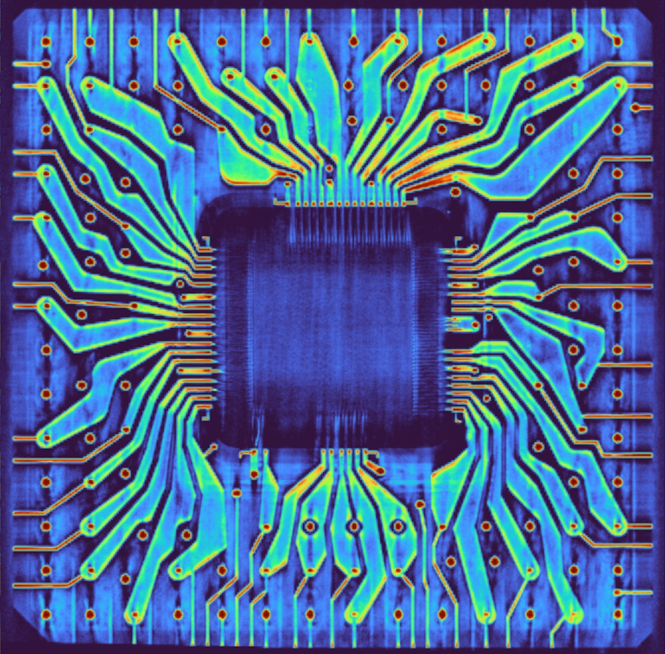


 for a larger version. Die photo from IEEE's Microchips that Shook the World exhibit page.")


 modulates the carrier (green), yielding the frequency-modulated output (blue). Created by Gregors, CC BY-SA 2.0.")


, lamp drivers (LD), more logic gates (2P/3G), and a flip-flop (LP FF). The modules have 13 staggered pins, ensuring that they can't be plugged in backward.")

 for a larger version. From Command/Service Module Systems Handbook p212.")

")


")


 with the case removed. This FDAI is on its side to avoid crushing the needles.")


 to the one in the FDAI.")


")
 with an ARU-11/A (bottom). The amplifier boards and needles have been removed from the FDAI.")


. The ADIs are indicated with arrows. The photo is from the National Archives.")


")

")


")
 for a larger version.")


 for a larger version.")


 organized into a grid.")

, separated by dotted lines. The small irregular squares are remnants of polysilicon
that weren't fully removed.")

. The striped green regions are the remnants of oxide layers that weren't completely removed, and can be ignored.")
 above two cells of type (d).")
, which can copy the value in the cell of type (b) below.")


 for a larger version.")


")


 and out of bit 2 (purple). Modification of the diagram by Robey Pointer, Wikimedia Commons.")


, electrostatic storage unit/frame (with circular storage CRTs). Right: printer, card punch. Photo from BRL Report, thanks to Ed Thelen.")
 is on the right. Photo from NOAA.")


 the central processor of the computer system. It contains the main storage, arithmetic unit and special register groups. Synonymous with (CPU) and (central processing unit). (2) All that portion of a computer exclusive of the input, output, peripheral and in some instances, storage units.")


.")
.")
 in mainframe panel 3 (MF3) section J, column 29.
The blocks shown are an AND gate, OR gate, and Cathode Follower (buffer).
From System Drawings 1.04.1.")

")
 could be rolled out of the frame (right)")
 for a larger version.")


 for a larger version.")
 and the polysilicon (faint gray).")

 and out of bit 2 (purple). Modification of the diagram by Robey Pointer, Wikimedia Commons.")


.")


.
Source: US Navy photo 80-G-41099.")
 a cage contains a winged rat. From Journeys to the Past, which describes Attenborough's visit to the island of Tanna.")


.")


_-_UNIZAR_-_Magnetic-core_memory_2Kbytes_IBM_360.jpg)
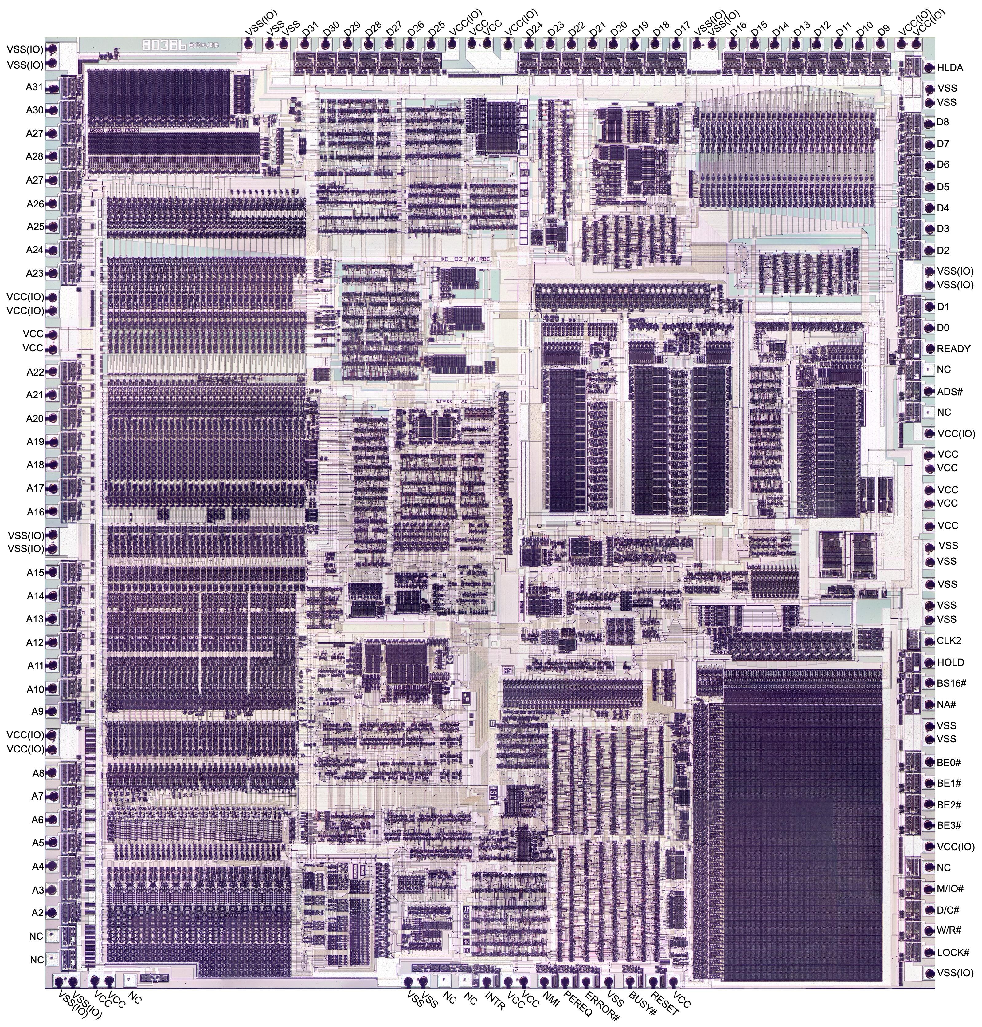
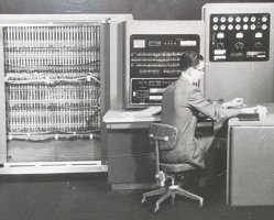