Ham RadioflrighamlibhamRadioic-7300packetRadiorigctl
I use flrig to control the IC-7300, which means that I can use the GUI […]
Show full content
I use flrig to control the IC-7300, which means that I can use the GUI to push buttons and turn knobs, but also use flrig to key the radio from BPQ for HF packet use.
If you have a rigctld daemon running, you can also use rigctl to send commands to flrig, on the local machine or over the network.
The key is to use -m 4-r localhost:12345, where 12345 is the flrig server port. Replace localhost with an IP if you are running remotely, and open the port in the your firewall.
So then you can run things like this:
rigctl -m 4 -r 192.168.0.6:12345 F 7104000 M LSB-D 800
Net105, 40M, 800Hz filter
rigctl -m 4 -r 192.168.0.6:12345 F 14105000 M LSB-D 800
Net105, 20M, 800Hz filter
rigctl -m 4 -r 192.168.0.6:12345 f
request frequency in Hz, for something like mwtchahrd
I haven’t figured out how to tune after changing bands, however.
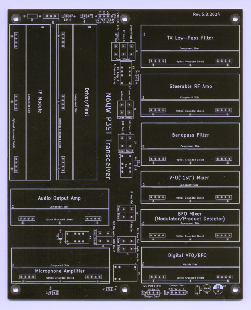
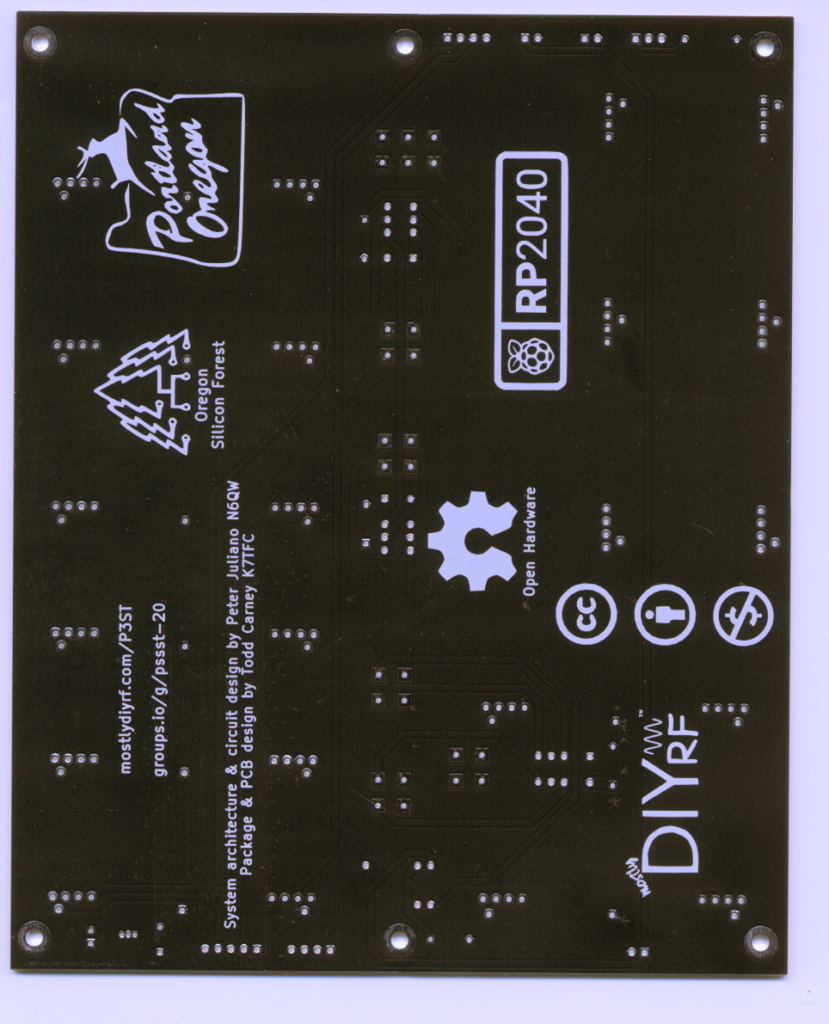
I will hopefully add more later about this project. See https://mostlydiyrf.com/p3st/. Note that the linked […]
Show full content
I will hopefully add more later about this project. See https://mostlydiyrf.com/p3st/. Note that the linked documentation on GitHub has been superseded in some cases by posts on the linked email group.
If you do enough different things with ham radio on Windows, eventually you'll run into a conflict between programs that can talk to your radio via something like flrig--and those that want the whole COM port to themselves.
Here are some example scripts that switch between 1) a packet radio environment (that uses UZ7HO SoundModem and BPQ32) using direct COM port access, and 2) a "regular" environment, in this case aimed at 20m CW operation. You could set up a script for each of your favorite operating environments if you wanted to.
Show full content
If you do enough different things with ham radio on Windows, eventually you’ll run into a conflict between programs that can talk to your radio via something like flrig–and those that want the whole COM port to themselves.
Here are some example scripts that switch between 1) a packet radio environment (that uses UZ7HO SoundModem and BPQ32) using direct COM port access, and 2) a “regular” environment, in this case aimed at 20m CW operation. You could set up a script for each of your favorite operating environments if you wanted to.
Hopefully these will be helpful to someone in the future, even as a lot of us move toward Linux (in which case rigctld and rigctl may be more directly useful). Keep in mind that they are not perfect and you should check them line-by-line to make sure they work for you.
For flrig, make sure you have the “Server” port configured (12345 in example) and all the boxes unchecked for “Restore.” These scripts assume you are running them on the same computer your radio is plugged into and flrig is on, otherwise you will have to replace the localhost IP and open the firewall for the port.
The full list of commands can be found here: http://www.w1hkj.com/flrig-help/xmlrpc_server.html. These commands go inside the <methodName></methodName> tags in the XML curl statements. The variable types (e.g. “n:n”) should match these tags that wrap the actual value inside <value></value>: n – nil (?), i – integer (32 bit, s – string, d – double (but I have not tested them all).
For this first draft, I skipped logic and just tried to close and reopen programs so I didn’t have multiple copies running. Timeouts are wait periods in seconds in case there are delays.
start "" "C:\Program Files (x86)\flrig-1.4.5\flrig.exe" timeout 1 :: Set frequency curl -X POST -d "<?xml version='1.0'?><methodCall><methodName>rig.set_frequency</methodName><params><param><value><double>14105000</double></value></param></params></methodCall>" http://127.0.0.1:12345
:: Set mode curl -X POST -d "<?xml version='1.0'?><methodCall><methodName>rig.set_mode</methodName><params><param><value><string>LSB-D</string></value></param></params></methodCall>" http://127.0.0.1:12345
:: Set power curl -X POST -d "<?xml version='1.0'?><methodCall><methodName>rig.set_power</methodName><params><param><value><int>50</int></value></param></params></methodCall>" http://127.0.0.1:12345
:: Set frequency curl -X POST -d "<?xml version='1.0'?><methodCall><methodName>rig.set_frequency</methodName><params><param><value><double>14050000</double></value></param></params></methodCall>" http://127.0.0.1:12345
:: Set mode curl -X POST -d "<?xml version='1.0'?><methodCall><methodName>rig.set_mode</methodName><params><param><value><string>CW</string></value></param></params></methodCall>" http://127.0.0.1:12345
:: Set power curl -X POST -d "<?xml version='1.0'?><methodCall><methodName>rig.set_power</methodName><params><param><value><int>20</int></value></param></params></methodCall>" http://127.0.0.1:12345
I had a cheap audio amplifier from AliExpress, a few speakers pulled out of an […]
Show full content
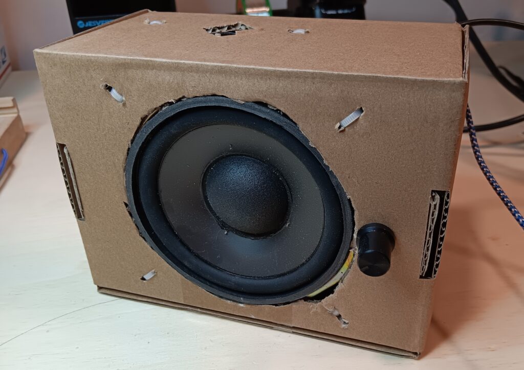
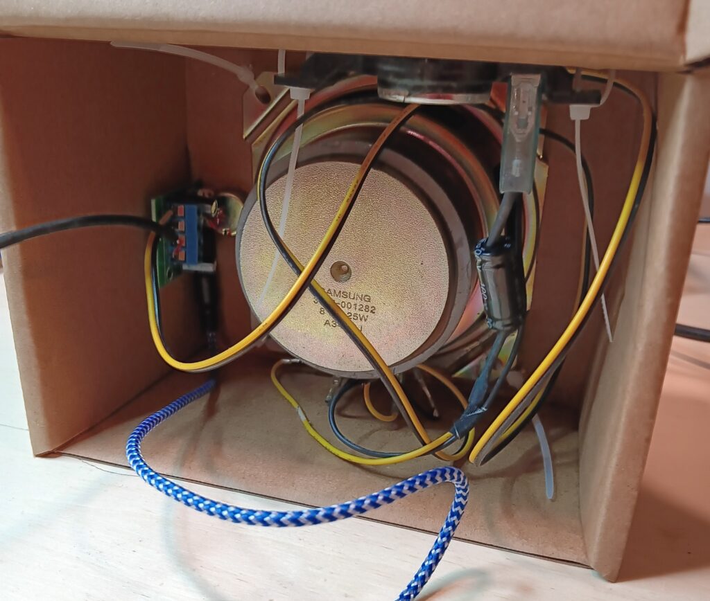
I had a cheap audio amplifier from AliExpress, a few speakers pulled out of an old TV, a chunk of USB cable, a cardboard box, and half an hour. Looks like I made something! Audio quality isn’t the best, but it will run on a 5V/1A USB power supply and I can plug a radio into it instead of using headphones.
Front view of a large TV speaker built into the front of a cardboard box and a smaller speaker built into the top. The speakers are held in place with zip ties. There is a black volume control knob to the right of the front speaker. A blue-cloth wire and a black wire exit the top right rear corner of the box.Rear view of the speaker in a box. There is a small audio amplifier PCB on the left side. The black wire, blue wire, and a yellow/brown wire from the speaker connect to this PCB. You can see the untrimmed zip ties.
Quick post to show this off. I needed a 70 cm antenna for packet radio […]
Show full content
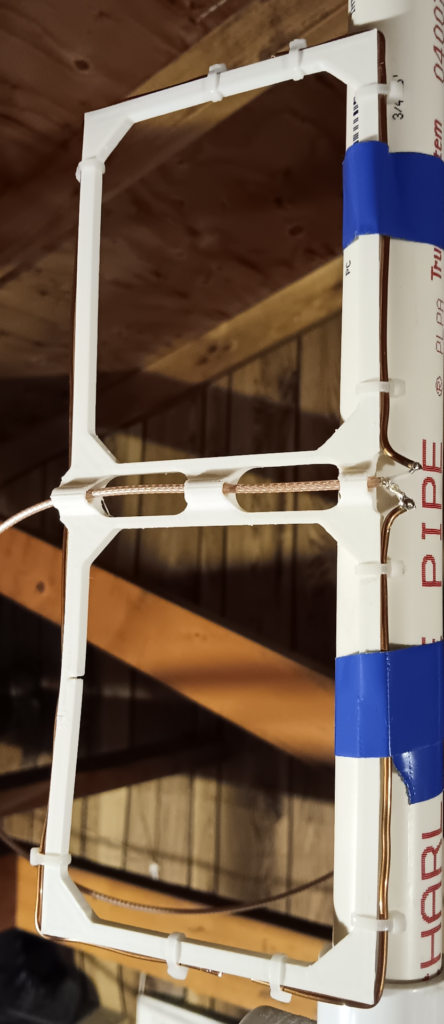
Quick post to show this off. I needed a 70 cm antenna for packet radio (maybe more on that later), and didn’t want to fiddle with a Yagi or a ground plane.
Using 14 gauge bare copper wire, it was a little rough getting the wire lengths right. I ended up matching the length for the reflector wire, but reduced the length of the driven elements to keep a 5 mm gap between the ends of the wires. I soldered a bit of RG-316 onto the driven elements and used a simple screw-terminal BNC connector on the end of the coax.
The nanoVNA says the SWR is below 2:1, and I didn’t check beyond that.
I have more notes if anyone is interested; in the interest of keeping things simple, here is a photo.
Photo of a vertical 430 MHz Moxon antenna, with copper wires zip-tied on to a 3D-printed frame. The coax comes through the middle and attaches to a split driven element on the right.
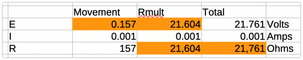
Let’s say the max voltage is what we would get for a 5W signal. Using Eq. 7.1 from “Experimental Methods in RF Design” (EMRD) which accounts for the 0.6V voltage drop across the diode. $P_{watts} = \frac{(V_{dc} + 0.6)^2}{2 \times R}$
So now we can go back to All About Circuits and figure out the resistor value. I did this in LibreOffice, orange cells are calculated using $E = IR$
Screenshot of a table of values relating E, I, R of the meter movement, multiplier resistor, and the total.
This indicates a 21.6K multiplier resistor.
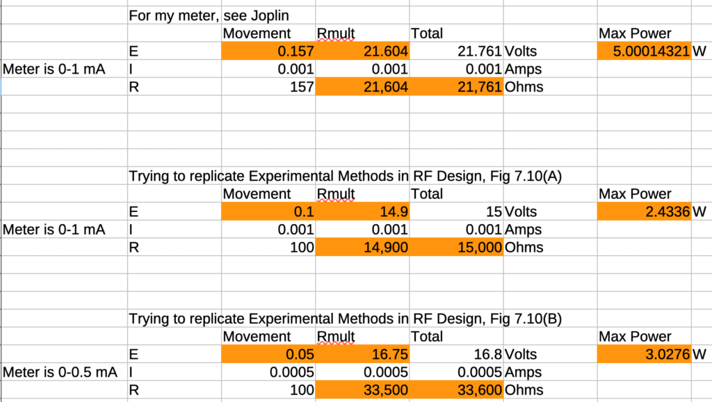
Looks like I can replicate EMRD with the same equation:
Screenshot of some more E, I, R tables, showing different inputs and outputs.
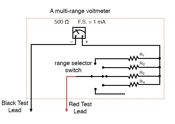
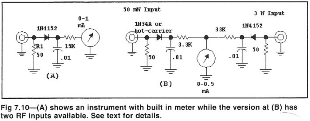
And of course, here’s the end product I’d like (from All About Circuits), a variation on the two-input meter shown in EMRD Fig. 7.10(B).
Image from All About Circuits, showing a meter schematic with a multi-selection switch leading to different resistors between the test lead and the meter.
Figure 7.10 from Experimental Methods in RF Design, showing a one-meter, one-input schematic and a one-meter, two-input schematic.
Next steps
The 50 $\Omega$ load needs to take the power, so I think I will have a dummy load port there.
The diode needs to have a breakdown voltage of (for these 5W max specs) greater than…what?
[ ] how to determine breakdown voltage and relationship to watts in this circuit.
Ham Radiocatci-vCWflrigic-7300paddleKeystraightKey
Mostly just copying this info over from my Mastodon account. I originally posted this: “Is […]
Show full content
Mostly just copying this info over from my Mastodon account. I originally posted this:
“Is there a way to send a CAT message to an IC-7300 to change from a straight key to a paddle, or is that out of spec for CAT? I can wire up both key and paddle on the desk, but it’s the 7 button presses on the radio that bug me.”
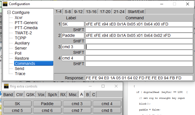
I realized at some point that I could set up shortcut command buttons in flrig, which I use for CAT control for most of my operations (excepting Winlink and packet). Here’s how I did it (Mastodon):
Screenshot of flrig “Configuration” and “flrig extra controls” windows, showing two commands–SK and Paddle–and the associated CI-V strings to make them happen.
Now what remains is to physically wire up the straight key and paddles together so both can be operated at the same time. Then switching is just a click away on flrig.
Thanks to Eric N2EPE, I recently learned about W4DD’s neat program for radio frequency interference […]
Show full content
Thanks to Eric N2EPE, I recently learned about W4DD’s neat program for radio frequency interference (RFI) mapping named, helpfully, “RFI Mapper.” I emailed him for a copy and got a quick reply with clear instructions. Thanks Jeff! Note that this is a Windows program.
While testing with my home station, and IC-7300, the only issue I ran into was that the radio would key whenever I ran the program. That makes it hard to measure and creates QRM! The cause was that I have RTS keying set up, probably something to do with Winlink and/or fldigi.
Anyway, here’s how to get to the RTS setting in case you (or me in the future) need to:
Menu (physical button)
Set
Connectors
USB Send/Keying
USB Send
Off (neither RTS nor DTS)
The program covers several models of radio, but the IC-7300 is the only one I have a cable for at the moment. This type of thing is intriguing from a “how many ways are there to do this” perspective, which gets my gears turning. For example, KA7OEI did a similar project back in 2001: http://www.ka7oei.com/ft817_rptmon.html (and props to Clint for keeping a website up these last 23 years!). Could we do it with an SBC or an Arduino? Could we do it with a QMX? Sounds like fun…
Also called a “DDS VFO.” This may be a bit of a brain dump. Although […]
Show full content
Also called a “DDS VFO.” This may be a bit of a brain dump. Although I have local notes (in Joplin), if I had to look hard for this stuff, maybe someone else can benefit from it. I’ll try to skip the details of the dead-ends I went down.
I put the Pixie kit I put together as a distraction from the thing that’s been bugging me, which is putting together some different modules in a receiver to 1) learn more about hardware and b) eventually design a radio orienteering receiver. (Why design when I can put together someone else’s design? Not sure yet.)
Building
In short, I took these building blocks and put them together:
Rotary encoder with push button from eBay (affiliate link)
Generic momentary contact button (originally from SparkFun kit)
High-pass filter that I designed and need to blog about
Although I don’t understand it all yet, the modification to the Pixie is explained at the very end of this “S-Pixie QRP Kit Student Manual.” Although I have the Pixie and not the S[uper]-Pixie, the component names matched the schematic I was provided with.
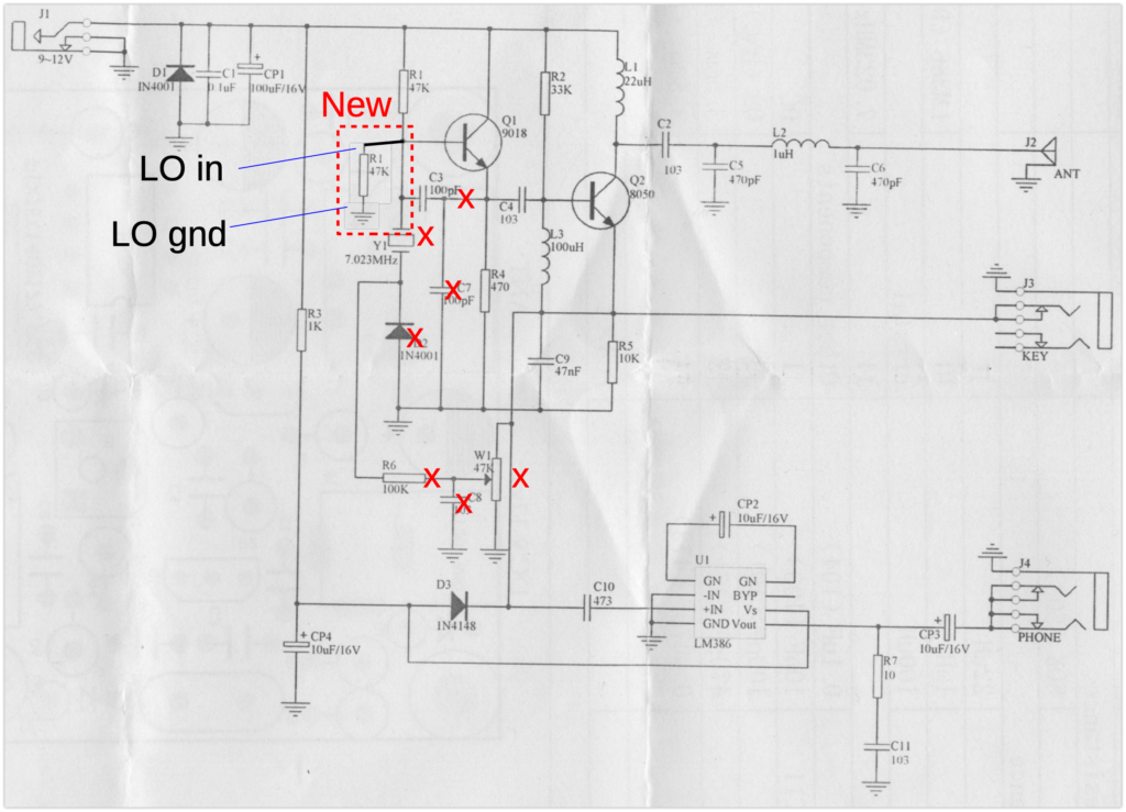
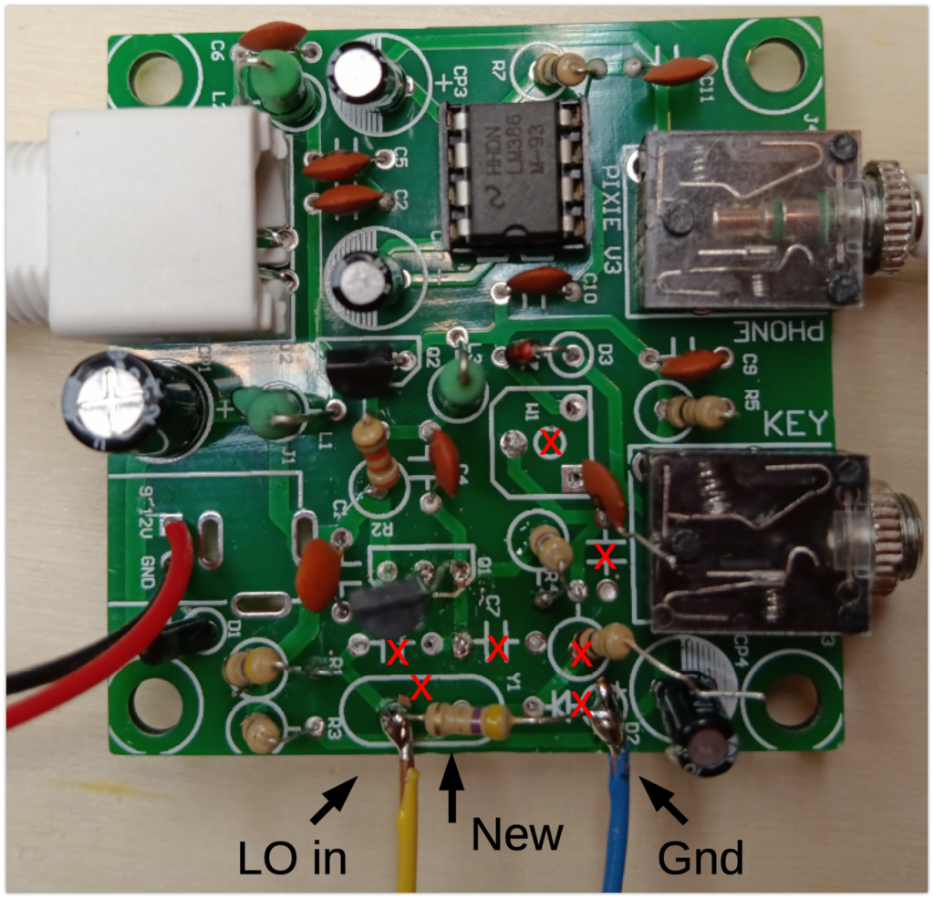
The S-Pixie can be modified to cover the whole 40 Meter band by replacing the oscillator with a VFO. A popular approach has been to use a Direct Digital Synthesizer (DDS) controlled by an Arduino. The human interface includes an LCD display and rotary encoder. Popular DDS choices include the AD9850 and the SI5351. Remove/Omit C3, C7, Y1, W1, D2, R6, and C8. Place a 47K resistor between Q1 base and GND. Connect the DDS across that resistor.
Schematic of the modified Pixie board, showing seven components that were removed (two were half-removed), one new resistor, and the wires for LO in and ground from the LO.Photo of the modified Pixie board, showing seven components that were removed (two were half-removed), one new resistor, and the wires for LO in and ground from the LO.
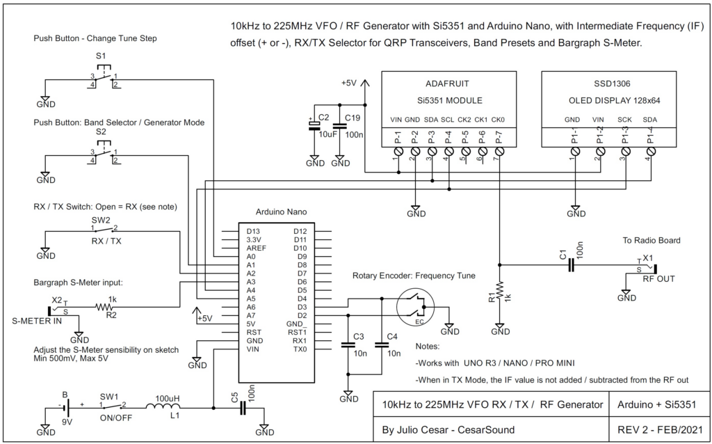
I don’t think I changed any of the code yet, but my version is here. I used the same pins CesarSound defined in the schematic below. I only used the connections from the Si5351 module, the OLED display, and the rotary encoder to the Arduino and ignored the rest. I skipped the capacitors across the rotary encoder connections.
Schematic from CesarSound of the connections from Arduino to Si5351 module and OLED.
Testing
I’m a bit overwhelmed, so you don’t get anything here right now.
here is where I talk about testing, maybe with audio/video
does it transmit
HPF to block broadcast AM – separate blog post
not great selectivity – hard to use for QSO
Next Steps
I have to keep reminding myself that this is not a product, it is a learning exercise. I do plan on making a standalone digital VFO module (with a board and case and all that) that can be plugged into other modules as needed. The digital VFO might use something smaller and cheaper than the Metro, like an ESP32 dev board, if I can get it to work. Pete N6QW has a bunch of information on this type of project.
The Pixie part may be modified/stripped down more so I can better understand it or re-use into another application.
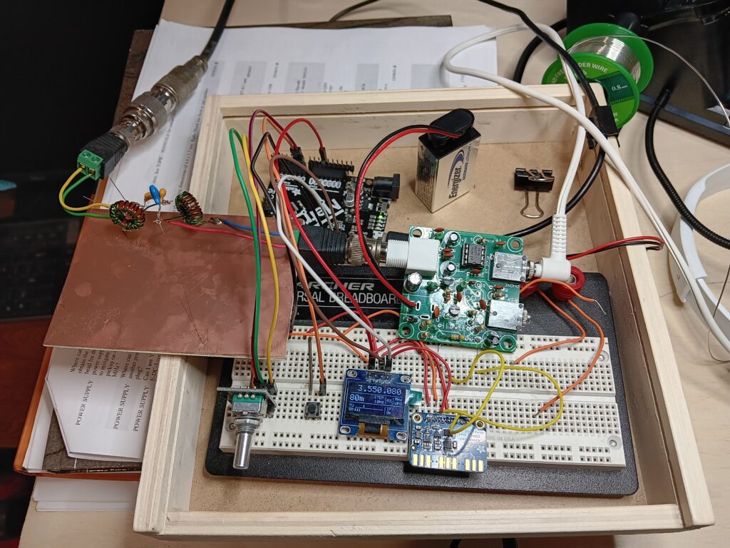
Photos
Photo of a solderless breadboard, an Adafruit Metro, a Pixie transceiver kit, and a copper board. The breadboard has an encoder, a button, an OLED, and an Si5351 board. The copper board has a homebrew high-pass filter on it. Coax runs from the filter off the top of the image. A 9V battery powers the Pixie. A black cable runs off the bottom to power the Metro/OLED/Si5351. It looks like a big old mess.