GeistHaus
log in · sign up

https://zamundaaa.github.io/feed.xml

atom
10 posts
Polling state
Status active
Last polled May 18, 2026 23:32 UTC
Next poll May 19, 2026 23:48 UTC
Poll interval 86400s
ETag W/"69fb4249-196a7"
Last-Modified Wed, 06 May 2026 13:29:45 GMT

Posts

Making wl_shm fast
Wayland
While most new applications use the GPU for rendering to achieve better performance and battery life, there are some new applications and a lot of older applications that still use CPU rendering. More specifically relevant for KDE, while QtQuick is GPU accelerated, QtWidgets uses CPU rendering.
Show full content

While most new applications use the GPU for rendering to achieve better performance and battery life, there are some new applications and a lot of older applications that still use CPU rendering. More specifically relevant for KDE, while QtQuick is GPU accelerated, QtWidgets uses CPU rendering.

With CPU rendering, instead of sharing GPU buffers with the compositor, wl_shm is used to present images. “shm” stands for “shared memory”, and is literally just some system memory allocated by the app and shared with the compositor.

Why is it slow?

The rendering speed of an application using CPU rendering depends a lot on what the application is doing exactly, but a very large factor is simply the sheer number of pixels and thus bytes it manipulates. With high resolution screens, especially single threaded CPU rendering can get pretty slow.

Optimizing the application side isn’t my area of expertise though, and not what I’m primarily interested in as a compositor developer. My main goal is to let the application render at whatever speed it can, and to efficiently transfer the results onto the screen.

On the compositor side we can’t normally use shm buffers directly. For the GPU to be able to access the data, we first need to copy it to a different buffer that meets the requirements of the GPU. This copy is often done in two steps:

  1. copy the data to a GPU-accessible buffer on the CPU
  2. copy that GPU-accessible buffer to another buffer in GPU memory

With both OpenGL and Vulkan, that first copy is blocking the main thread until it’s complete. You can offload the copy to a different thread with some additional code, but that would just move the CPU usage, rather than reduce it.

The second copy is more acceptable, since the GPU does it asynchronously and more efficiently, but on integrated GPUs, this would still end up copying data from system memory to a different region of system memory, for no good reason.

The result of these copies is that on high resolution screens with applications using shm buffers, performance noticeably suffers and CPU usage is much higher than it has any right to be.

On my laptop with a still relatively new and high end Ryzen 7840U, I could see the cursor sometimes skip frames when quickly moving it over project files in KDevelop, since KWin’s main thread was being blocked by these texture uploads. Normally that’s not really noticeable, but with the power profile set to “power save”, it felt really sluggish.

Vulkan will fix it… right?

When you hold a hammer, every problem starts to look like a nail.

Since we recently started using Vulkan in KWin to fix some other problems caused by OpenGL’s inadequacies1, I obviously looked for a Vulkan solution first. And lo and behold, VK_EXT_external_memory_host does exist, and it’s perfect for this! Or at least it looked like it would be…

The extension allows wrapping a “host pointer” (aka a normal pointer to CPU memory) in a VkBuffer or even VkImage2. With a pretty low amount of new Vulkan code, the GPU could asynchronously copy the VkBuffer to a GPU-local buffer.

Unfortunately, the implementation at least on AMD comes with some limitations. Because of potential security issues, pointers to anything associated with a file descriptor (which shm buffers always are) can’t be imported this way by amdgpu.

There is also the more recent VK_EXT_host_image_copy for optimizing image uploads, but it would only allow removing the second copy rather than the first, so it’s not exactly what I needed.

udmabuf to the rescue

udmabuf is a Linux driver that can wrap memfd-allocated memory in a dmabuf. A dmabuf is a handle to GPU memory, and memfd is how shm buffers are usually allocated by Wayland clients… so it’s a perfect fit for what I wanted to do.

There’s one caveat to this: In order to be able to create a udmabuf from it, the allocated memory must be a range of memory pages3, so location and size have to be a multiple of the page size. Applications didn’t allocate their buffers with that in mind so far, since there was no benefit to it. Fixing that isn’t difficult though! Assuming one memfd per shm buffer (which at least Qt does), fulfilling the page size requirement should even be free4.

With the udmabuf successfully created, we can wrap it into a VkBuffer and do an asynchronous copy to a GPU-local buffer with Vulkan. However, we can do even better: If the stride5 of the buffer matches the requirements of the driver, we can directly use the udmabuf with the GPU.

This stride requirement is a bit more of a tradeoff than the page size one, since some additional memory may need to be allocated as padding at the end of each row in the image. Since most GPUs seem to be fine with a multiple of 256, the amount of “wasted” memory is still pretty low however - for example with a 3841x2160 image, it would be 0.55MB or 1.6% more memory used per buffer.

So I added code to KWin to attempt to create a udmabuf for each shm buffer, and then import that into the GPU driver. If it fails, we just fall back to the old upload code, but if it succeeds, we don’t need to do any copies at all.

The compositor side didn’t take a lot of code, but the application side was much simpler still. Including a comment explaining the reasoning, it merely took a grand total of 18 changed lines of code.

The result

With the same example of KDevelop I mentioned before, the cursor is now always completely smooth. In terms of concrete numbers, KWin’s CPU usage while scrolling in KDevelop went from 80-90% on one core down to 20%!

These improvements will be in Plasma 6.7 and Qt 6.11.2. I would recommend other toolkits and applications that use shm buffers to make the same changes as I did in Qt, it can make a really noticeable difference.


  1. I’ll write a blog post about it once there’s more to talk about 

  2. With a Vulkan renderer, the VkImage would mean the second copy could be skipped as well 

  3. A page is the smallest chunk of contiguous memory managed by the OS 

  4. The kernel allocates in pages, so the amount of memory used should be the same either way 

  5. Stride is how many bytes are used by each row of pixels in an image. There can be unused padding after each row, which is included in the stride. 

https://zamundaaa.github.io/wayland/2026/05/06/making-wl-shm-fast
Automatic brightness in Plasma
Wayland,Display
As an exception to my usual posts, this time I’ll write about a feature that’s already released. Since Plasma 6.6, you can enable automatic brightness in the display settings… let’s take a look at how it works, and why it took so long to make it happen.
Show full content

As an exception to my usual posts, this time I’ll write about a feature that’s already released. Since Plasma 6.6, you can enable automatic brightness in the display settings… let’s take a look at how it works, and why it took so long to make it happen.

The hardware

This is where the problems start - most laptops unfortunately don’t come with a brightness sensor, and there’s effectively no monitors that have a built-in sensor either (let alone one that can be accessed by the connected PC).

While it’s possible to buy or build a brightness sensor that connects via USB, brightness control for external monitors usually has limitations in how often we can safely adjust the brightness… So for quite some time, there was noone working on Plasma that had the combination of hardware, motivation and knowledge to do something about it.

Luckily, the Framework Laptop 13 comes with a brightness sensor, so on the hardware side I was all set:

Framework 13

The software

Making automatic brightness do something is easy, but making it work well enough that you actually want to use it is a very different story.

My first approach was to assume brightness of the display should scale linearly with environmental brightness. I tried this, and it was sort of usable, but just not good enough. There’s three problems with it:

  1. the brightness setting sadly does not linearly control display luminance. 0% is generally not “off”, and sometimes firmware or drivers make the curve non-linear to make the brightness more “intuitive”
  2. in order for automatic brightness to be easy to use, we can’t expect the end user to configure an equation for their system. We need to automatically detect what they’re doing, and configuring two parameters based off one brightness slider is a challenge
  3. the best brightness curve isn’t necessarily linear. Depending on your personal preferences and how reflective your display is, you might want to keep brightness a lot higher in bright environments than in dark ones, or vice versa.

So a different approach was needed. I looked a bit at other operating systems for inspiration, and from the UX side I definitely wanted to copy Android: You use the brightness slider however you want, and the system should try to replicate what you do on its own. On the implemtation side however, I only saw claims that it uses machine learning, so that wasn’t exactly helpful.

Ultimately, what I settled on is pretty simple: We just store 6 sensor values, one per 20% brightness step. When processing sensor readings, KWin finds the matching brightness setting by linearly interpolating between the two closest sensor values.

final brightness curve

When the user touches the brightness slider or uses the brightness shortcuts, KWin adjusts the curve so the current sensor value will result in that desired brightness setting. At first, I only made it adjust the two closest points and enforce the rest of the curve to be monotonic, but it ended up causing problems:

full brightness issue

With this configuration, any sensor readings above 100 lux - for example, 101 - resulted in 100% brightness. To fix that, we now enforce a minimum difference of at least 1 lux or 10% between control points, so the curve above would look more like

full brightness issue fixed

To ensure the curve would always stay strictly monotonic and so you can have an arbitrary backlight setting at zero lux, values below zero also had to be allowed when updating the curve with those constraints.

However, I was still not done. While it now followed my preferences pretty well, it was still annoying! Especially if you sit in between a light source and the laptop, or if you sit on a train with trees around the tracks (like I recently did, traveling to and from Graz for a Plasma sprint), the brightness constantly fluctuated up and down.

To make it less annoying, I added some more adjustments on top:

  • some hysteresis. As long as the sensor reports ±10% of the last value, KWin should do nothing
  • a time delay before changes get applied. If after two seconds the sensor value is back in that 10% range, the brightness stays unchanged
  • a much slower animation for reducing display brightness (but not that much slower for increasing it)

This is how it was released in Plasma 6.6, and I’m pretty happy with it on both the Framework 13 and on my OnePlus 6 with Plasma mobile.

What now?

Just because I’m happy with it, doesn’t mean it’s done. If you’re using automatic brightness and it’s still annoying you for some reason, please tell me about it! If you’re really happy with it, I won’t complain about being told that either of course ;)

To fully catch up to what phones have done for years though, one feature is still missing: I’d like to adjust not just the brightness, but also the white point of the display to the environment. Unfortunately, none of my devices have a sensor for that… but since the camera module in the Framework 13 is easy to replace, I hope that changes one day!

https://zamundaaa.github.io/wayland,display/2026/04/24/automatic-brightness
More KMS offloading, with overlay planes
Wayland
In preparation for, and at the 2025 display next hackfest, I did a bunch of hacking on using more driver features for improved efficiency and performance. Since then, I polished up the results a lot more, held a talk about this at XDC 2025 and most of the improvements are merged and now released with Plasma 6.5. Let’s dive into the details!
Show full content

In preparation for, and at the 2025 display next hackfest, I did a bunch of hacking on using more driver features for improved efficiency and performance. Since then, I polished up the results a lot more, held a talk about this at XDC 2025 and most of the improvements are merged and now released with Plasma 6.5. Let’s dive into the details!

Using more planes

The atomic drm/kms API exposes three important objects to the compositor:

  • connectors, which simply represent the connection to the display. In most cases there’s one per connected display
  • CRTCs, which roughly represent the machinery generating the data stream that’s sent to a display
  • planes, that are used to define which buffers are composed in which way to create the image on a given CRTC. There’s three types, primary, cursor and overlay planes

When trying to drive a display, the compositor needs to put buffers on at least one primary plane, connect it to a CRTC, connect that to a connector, and then do an atomic test to find out if that configuration can actually work. If the configuration doesn’t work, because of hardware or driver restrictions, the compositor needs to fall back to a different (usually simpler) one.

Up to Plasma 6.4, KWin (mostly1) only used primary and cursor planes. Using the GPU, it composited all the windows, decorations and co. into one buffer for the primary plane, and the cursor into another buffer for the cursor plane. Whenever the cursor plane wasn’t available or the configuration using it didn’t work, it would fall back to compositing the cursor on the primary plane instead (which is usually called a “software cursor”).

Why even use multiple planes?

While compositing everything with the GPU allows for fancy features, color management, blur, wobbly windows and more, it does require the GPU to process lots of data. Depending on the hardware, this may be somewhat slow or incredibly fast, but it always takes some amount of time, and often uses a lot of power.

By using a plane for the cursor for example, when you move it, the compositor doesn’t have to re-render the screen, but it can just set the new cursor position on the hardware plane, which basically immediately changes the image that’s sent to the screen - reducing both latency and power usage.

In other cases we don’t really care about latency so much, but power usage is more important. The best situation is possible with video playback: If the application uses hardware decoding and passes the decoded video to the compositor unmodified, it can put the video directly on a plane, and the rest of the GPU can completely turn off! This already works in fullscreen, but with more planes we could do it for windowed mode as well.

So now you know why we want it, but getting there was a longer story…

Preparing the backend

Our drm backend had a relatively simple view of how to drive a display:

  • every output had one primary and one cursor layer, with matching getters in the render backend API
  • this layer wasn’t really attached to a specific plane. Even if your hardware didn’t have actual cursor planes, you’d still get a cursor layer!
  • when rendering, we adjusted to the properties of the actually used plane, and rejected rendering layers without planes
  • when presenting to the display, the code made assumptions about which planes need which features

This was quite limiting. I refactored the backend to instead create a layer for each plane when assigning a plane to an output, have a list of layers for each output, and treat all of them nearly exactly the same. The only difference between the layers is now that we expose information about how the compositor should use them, which is mostly just passing through KMS properties, like the plane type, size limitations and supported buffer formats.

Last but not least, I changed the backend to assign all overlay planes whenever there’s only one output. This meant that we could use overlay planes in the most important case - a single laptop or phone display - without having to deal with the problems that appear with multiple screens. This restriction will be lifted at some later point in time.

Preparing compositor and scene

The next step was to generalize cursor rendering - compositor and scene both had a bunch of code specifically just about the cursor, listening to the cursor image and position changing and rendering it in a special way, even though it was really just another Item, just like every window decoration or Wayland surface. I fixed that by adding the cursor item to the normal scene, and adding a way for the compositor to hide it from the scene when rendering for a specific output. This allowed me to adjust the compositing code to only care about item properties, which could then be reused for different things than the cursor.

As the last cursor change, I split updating the cursor into rendering the buffer and updating its position. The former could and should be synchronized with the rest of the scene, just like other overlays, but the latter needs to be updated asynchronously for the lowest possible latency and to keep it responsive while the GPU is busy. With that done, the main compositing loop could use primary and cursor planes in a rather generic way and was nearly ready for overlays.

Putting things on overlays

The main problem that remained was selecting what to put on the overlay planes that are available. There are some restrictions for what we can (currently) put on an overlay:

  • the item needs to use a dmabuf, a hardware accelerated buffer on the GPU
  • the item needs to be completely unobstructed
  • the item can’t be currently modified by any KWin effect

To keep things simple and predictable, I decided to just make KWin go through the list of items from top to bottom, take note of which areas are obstructed already, and find items that match the criteria and get updated frequently (20fps ore more). If there are more frequently updated items than planes, we just composite everything with the GPU.

Last but not least, we do a single atomic test commit with that configuration. If the driver accepts it, we go ahead with it, but if it fails, we drop all overlays and composite them on the GPU instead. Maybe at some point in the future we’ll optimize this further, but the main goal right now is to save power, and if we have to use the GPU anyways, we’re not going to save a lot of power by merely using it a little bit less.

Putting things on underlays

The concept of underlays is quite similar to using overlay planes, just instead of putting them above the scene, you put them below. In order to still see the item, we paint a transparent hole in the scene where the item would normally be.

This is especially useful whenever there is something on top of the item that isn’t updating as frequently. The best example for that is a video player with subtitles on top - the video updates for example 60 times a second, but the subtiles only once every few seconds, so we can skip rendering most of the time.

There isn’t really that much more to say about underlays - the algorithm for picking items to put on overlays needed some minor adjustments to also deal with underlays at the same time, and we needed to watch out for the primary plane to have enough alpha bits for semi-transparent things (like window shadows) to look good, but overall the implementaiton was pretty simple, once we had overlay plane support in place.

The result however is quite a big change: Instead of getting an overlay in some special cases, KWin can now use planes in nearly all situations. This includes the newly introduced server-side corner rounding in Plasma 6.5! We simply render the transparent hole with rounded corners, and we can still put the window on an underlay with that.

There is one thing that did not land in time for Plasma 6.5 however: The current algorithm for underlays only works on AMD, because amdgpu allows to put overlay planes below the primary one. I have an implementation that works around this by just putting the scene on an overlay plane, and the underlay item on the primary plane, but it required too many changes to still merge it in time for Plasma 6.5.

Required changes in applications

Most applications don’t really need to change anything: They use the GPU for rendering the window, and usually just use one surface. If the entire window is getting re-rendered anyways, like in the case of games, putting the surface on an overlay or underlay is quite simple.

There are however some situations in which applications can do a lot to help with efficiency. If you’re not already using the GPU for everything, you’ll want to put the quickly updating parts of the app on a subsurface. For example, mpv’s dmabuf-wayland backend puts

  • the video background on one surface with a black single pixel buffer
  • the video on separate surface
  • playback controls and subtitles on another separate surface

which is the absolute best case, where we can basically always put the video on an underlay. If the video is also hardware decoded, this can save a lot of power, as the GPU can be completely turned off.

You also want to support fractional scaling properly; while some hardware in many situations is fine with scaling buffers to a different size on the screen, there are sometimes hardware restrictions on how much or even if it can scale buffers.

Using drm color pipelines

The described overlay and underlay improvements are great… but have one big flaw: If presenting the Wayland surface requires color transformations, we have to fall back to compositing everything on the GPU.

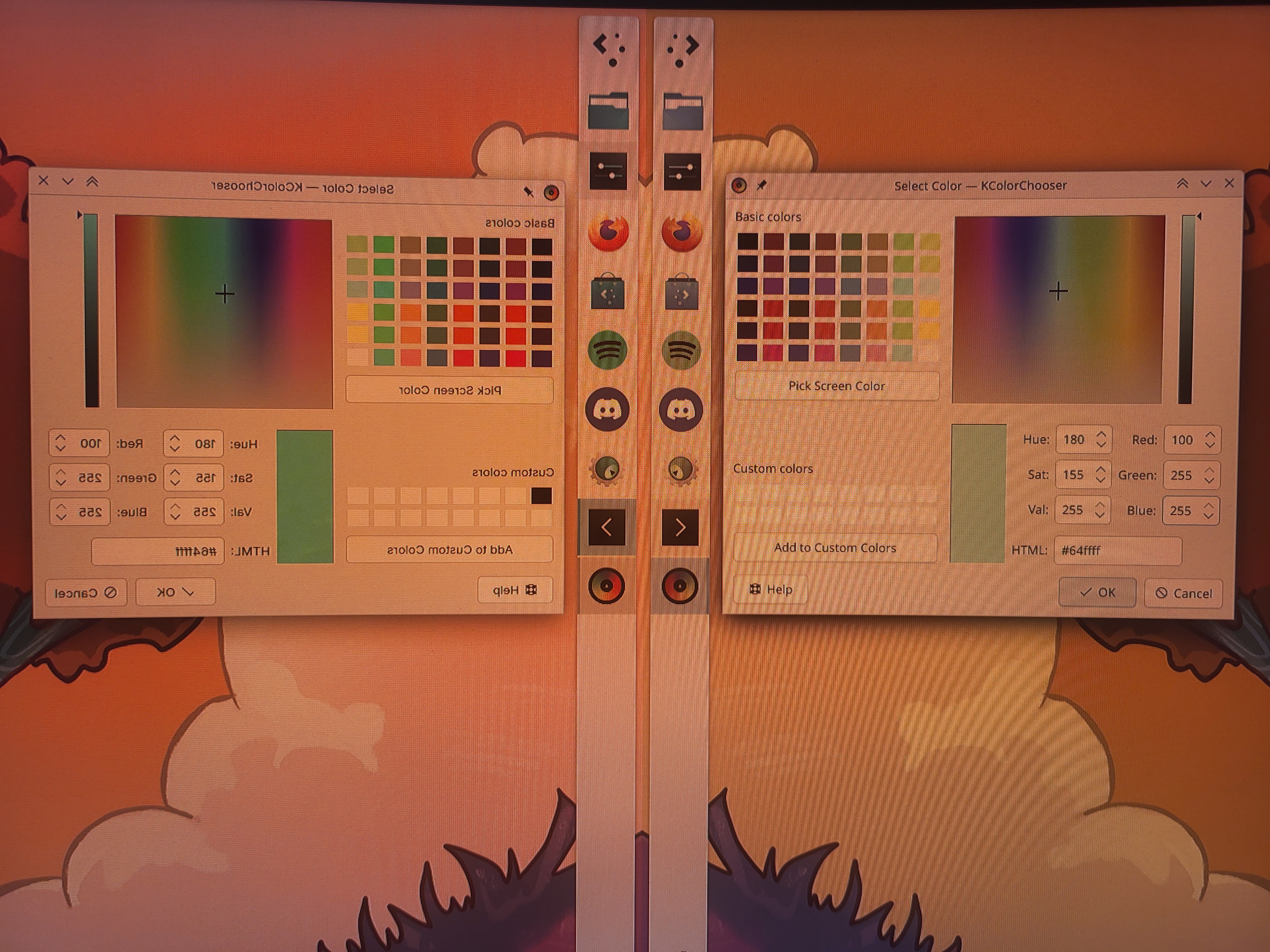
Luckily, most GPU hardware can do some color operations on the planes. The API for those color operations has been worked on for a long time, and I implemented support for it in KWin. With the relevant kernel patches, KMS exposes color pipelines - each a list of color operations, like a 3x4 matrix or per-channel 1D and 3D lookup tables, which the compositor can program in whatever way it wants. Every time we attempt to put an item on a hardware plane, we also attempt to match the required color transform to the color pipeline.

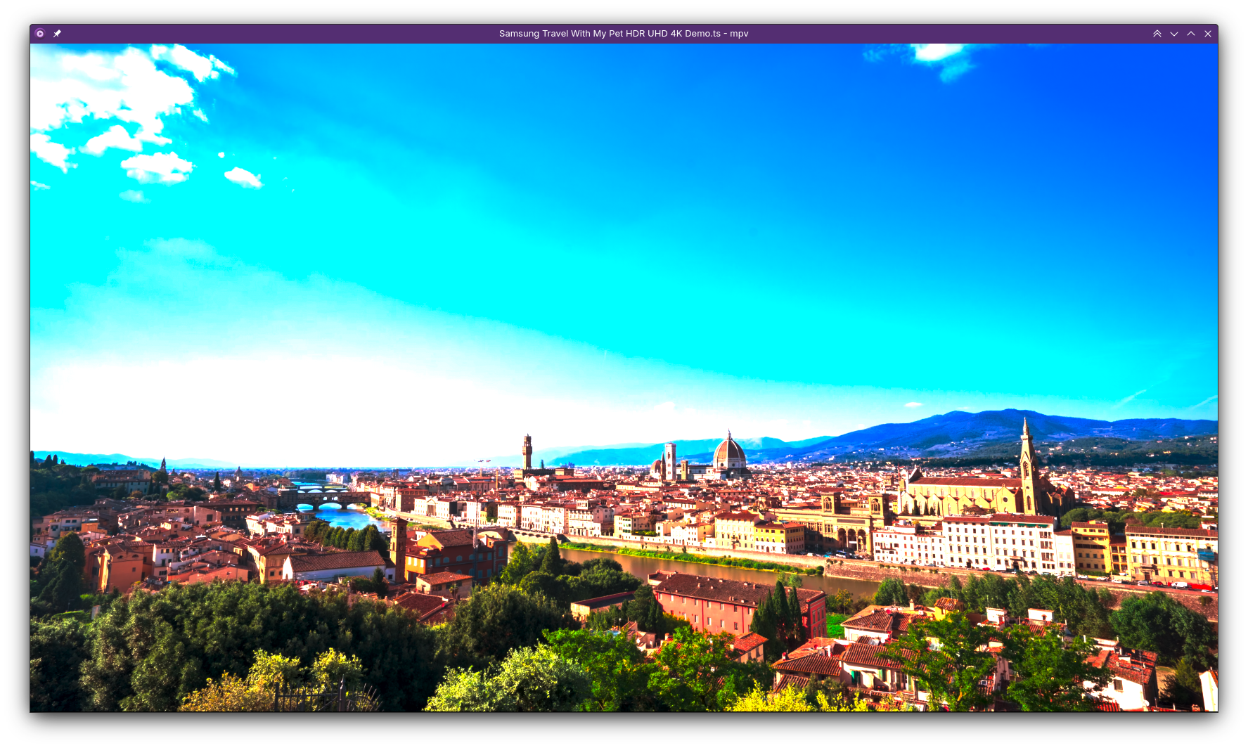
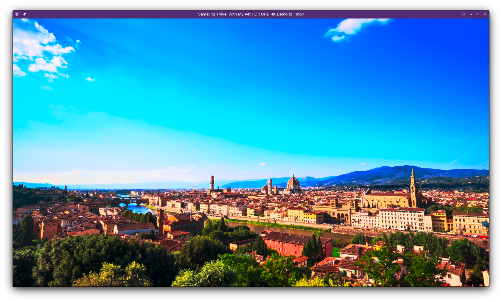
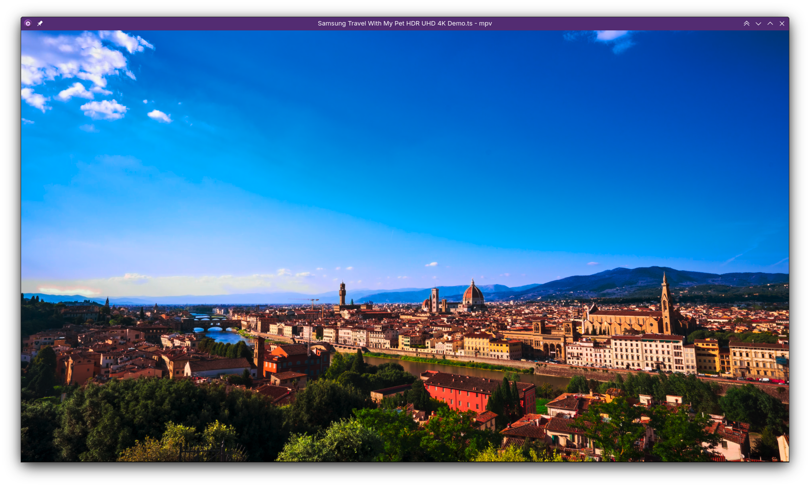
With the patchset for that, on my AMD laptop I can open an HDR video in mpv, and even if the video has subtitles, is partially covered by another window and the screen is SDR, the video is presented correctly without the GPU being involved!

How much does it really help?

Now the most interesting part: How much power does this actually save in the long run? I did some measurements with all the patches put together.

To test this, I played each video on a Framework 13 at 50% display brightness, with “Extended Dynamic Range” enabled and the keyboard backlight turned off, and recorded the power usage from the sysfs interfaces for battery voltage and current. The results you see in the table are the averages of 15 minutes of video playback, so the numbers should be pretty reliable.

On the application side, I used YouTube videos in Firefox with gfx.wayland.hdr enabled. As YouTube didn’t allow me to play HDR videos for some reason, I used mpv with the dmabuf-wayland backend to play back a local video instead.

Video without overlays with overlays 4k SDR in Firefox 13.3W 11.5W 1080p SDR in Firefox 11W 9.6W 4k HDR in mpv 13.4W 12.4W

Or in terms of (estimated) battery life:

Video without overlays with overlays 4k SDR in Firefox 4.6h 5.3h 1080p SDR in Firefox 5.5h 6.4h 4k HDR in mpv 4.6h 4.9h

As a reference for these numbers, the laptop being completely idle with the same setup uses about 4.5W, which equals about 13.5 hours of battery life. So while this is a good start, I think there’s still a lot of space to improve. At XDC this year I was told that we may be able to do something about it on the application side by using the hardware decoder more efficiently; I’ll do another run of measurements whenever that happens.

When can I start to use this?

Due to various driver issues when trying to use overlays, like slow atomic tests on AMD as well as display freezes on some AMD and NVidia GPUs, this feature is still off by default.

However, if you want to experiment anyways or attempt to fix the drivers, starting from Plasma 6.5, you can set the KWIN_USE_OVERLAYS environment variable to enable the feature anyways. If you test it, please report your findings! If there’s problems in the drivers, we’d like to know and have bug reports for the GPU vendors of course, but also if things work well that would be nice to hear :)

When we can enable it by default isn’t quite clear yet, but I hope to be able to enable it by default on some drivers in Plasma 6.6.


  1. If there was no cursor plane, it was able pick an overlay plane instead, but that was it. 

https://zamundaaa.github.io/wayland/2025/10/23/more-kms-offloading
Display Next Hackfest 2025
Wayland
This year there was another “Display Next Hackfest”, this time thanks to AMD organizing and hosting the event at their office in Markham, Toronto. Just like the last hackfests, there were other compositor developers and driver developers present, but in addition we had the color experts Charles Poynton and Keith Lee to pester with questions, which was very useful. In general, the event was very productive.
Show full content

This year there was another “Display Next Hackfest”, this time thanks to AMD organizing and hosting the event at their office in Markham, Toronto. Just like the last hackfests, there were other compositor developers and driver developers present, but in addition we had the color experts Charles Poynton and Keith Lee to pester with questions, which was very useful. In general, the event was very productive.

Picture of the hackfest room

We discussed a lot of things, so this is just a summary of what I personally consider most important, not exhaustive notes on every topic. You can read the full notes on Harry’s blog.

Commit Failure Feedback

Currently, when the compositor tries to commit changes to KMS and that fails, it almost always just gets -EINVAL as the response, in other words “something doesn’t work”. That’s not just annoying to debug, but can lead to the compositor spending a lot of time with useless atomic tests in some situations, like for example when KWin tries to turn displays on - I’ve seen cases where we spend multiple seconds testing every possible configuration of outputs (while the screen is frozen!), just for the actual problem to be unfixable without turning one of the displays or some feature off.

So we discussed how to improve on that, and the result was basically that we just want something - really anything is better than the current situation. We found that there’s a reserved field in the atomic ioctl, so we can even do this without introducing a completely new ioctl and just make that reserved field an optional pointer to another struct in which the kernel will write the feedback on what failed exactly. The most basic things we agreed to start with are to return

  • some enum for common issues, like limited scanout/memory bandwidth, limited connector bandwidth, invalid API usage, things like that
  • some string with possibly driver-specific information that the compositor can log, most important for debugging problems on user systems
  • an optional array of KMS object IDs for what objects are related to the failure, for example for which connectors are hitting bandwidth limits
New Backlight API

The current backlight API on Linux is that the kernel exposes one or multiple backlight related files in sysfs, and userspace writes to one of them with root permissions. This requires heuristics for which one of the files is the correct one to use, this API can only control a single backlight, it can’t be synchronized to the image a compositor presents, the firmware may or may not do animations, it may be linear or not, the minimum brightness is completely undefined (sometimes it’s zero!), in summary it’s a total mess.

Three years ago there was a proposal to add a backlight API to KMS instead, which however stalled as the author had to work on other tasks. We discussed on what exactly we want from that API:

  • a backlight property per connector
  • optional additional information about the mapping of backlight values to actual luminance (min/max values, linear/nonlinear curve)
  • (where possible) no animations in the firmware
  • (where possible) atomically update the backlight with the rest of the atomic commit, so we can properly synchronize content and light level for HDR on SDR displays
Adaptive Backlight Management

ABM is a feature on some AMD hardware, which reduces backlight intensity to save power and at the same time increases contrast of colors on the screen to compensate for that reduced backlight level. This is a bit of a controversial feature - on one hand it improves battery life, but on the other it messes with the colors on your screen, which to some people just doesn’t look good but is really bad if you’re trying to do color critical work.

Currently this feature is controlled through sysfs, which means power management daemons can mess up your colors without you being aware. Additionally it would be nice to automatically turn off the feature when you’re profiling your screen with a colorimeter, and as the feature reduces the backlight, also in very bright environments to get that extra brightness… To improve on that situation, we’ll get a KMS property to control the feature from the compositor side. I intend to make it off by default in Plasma, but users that want additional battery life will be able to easily opt into it in the display settings.

Autotests

We had three discussions about automatic tests - one about measuring power usage, one about testing KMS drivers, and one about testing compositors.

For power usage tests, we didn’t really agree on the best way to get a standardized testing framework, but we found some possible approaches that can work now - tests can be automated to some degree by using compositor-specific APIs, the remote desktop portal or OpenQA.

For testing KMS drivers, we talked a bit about how the IGT test suite is useful for testing specific cases, but it doesn’t really cover all the same bits that real world compositors use. The tests mostly use features in a somewhat self-contained manner, are mostly written by kernel developers, and thus test how they expect their APIs to be used, which is sometimes different from how compositors actually use it. A possible solution for that is for compositor developers to write automatic tests using their compositor, which run directly on KMS and execute some pre-programmed sequence of events, possibly requiring KMS features like color pipelines or overlay planes to be used successfully for the test to pass.

We still have to figure out the details, but if we can get compositors in DRM CI, that could help improve stability of both compositors and drivers.

Last but not least, for testing compositor’s KMS usage, we can’t really rely on our manual testing with actual hardware, and DRM CI tests will still be somewhat limited. Some compositors already use VKMS, a virtual KMS driver, for their automatic tests, and there are some pending kernel changes for configuring it to do a lot more than the rather simple and fixed setup we had so far. With the new API, we’ll be able to configure it to have nearly arbitrary amounts of planes, add and remove connectors and even entire GPUs! I still have to wire up a KWin autotest for this, but it will be very useful both in development and to prevent regressions in releases.

Color and HDR

We of course also spent a lot of time talking about color management and HDR, and started that off with the current state of implementations. Things are looking really good!

In terms of Wayland protocols, all the important bits are in, namely the color management and color representation protocols. There may still be some smaller changes to the protocols, maybe some additions here and there, but the most important parts are done and used in practice. If you’ve read my previous blog posts, you might know that KWin’s color management story is in a really good state, but other compositors are getting there as well. While Mutter is still lacking non-HDR color management bits, it now has basic HDR support, the Cosmic compositor has some preparations for it going on under the hood, and wlroots has basic HDR support as well.

On the application side, lots of applications are working on supporting it, like Qt, GTK, Godot and Firefox, or support it already, like Mesa, mpv and gamescope. Notably, Blender even has currently Wayland-exclusive HDR support!

We had a Q&A and some discussions with Charles Poynton and Keith Lee. For details you can look at the notes, but the most important thing I took from it was that we should adapt visuals to the user’s viewing environment based on their absolute luminance too, not just the relative light levels. How to actually do that adjustment in practice isn’t entirely figured out yet though, so that will be an interesting problem to solve.

We also talked a bit about the drm color pipeline API. I won’t go into details about this one either, but I’ll talk more about it my next blog post. TL;DR though is that this API allows us to use many more color operations that GPUs are capable of, to avoid compositing with shaders in more situations. I have a KWin implementation that proves the API works and by now the API and driver implementations basically just have to be merged into the kernel.

My “Favorite”: Pageflip Timeouts

Judging by how often I come across this issue in bug triage, if you’re reading this, chances aren’t too terrible that you’ve heard of this one already, possibly even seen it yourself in the form of

kwin_wayland_drm: Pageflip timed out! This is a bug in the amdgpu kernel driver
kwin_wayland_drm: Please report this at https://gitlab.freedesktop.org/drm/amd/-/issues
kwin_wayland_drm: With the output of 'sudo dmesg' and 'journalctl --user-unit plasma-kwin_wayland --boot 0'

in your own system logs at some point. To be clear, this is just an example and it does not only affect amdgpu. I’ve seen the same with NVidia and Intel too, but as amdgpu’s GPU resets have been a lot less reliable in the past, it’s been a bigger issue for them.

Basically, pageflip timeouts are when the compositor does an atomic commit through KMS, and then waits for that to complete… forever. When this happens, the kernel literally doesn’t allow the compositor to present to the screen anymore, so the screen is completely frozen forever, which is very bad, to state the obvious.

Fixing all the individual causes of the problem hasn’t really worked out so well, and this is a bad enough situation that there should be a way out when it does happen. We discussed how to do this, and I’m happy to report that we figured out a way forward:

  • we need a new callback in KMS that tells compositors when a pageflip failed and will never arrive
  • drivers need to support resetting the display-driver bits of the GPU to recover it
  • if the driver entirely fails to recover in the absolute worst case, it should send a device wedged event, which tells the compositor it should try to reload the entire driver / device
Scheduling Atomic Commits

When presenting images to a display, compositors try to get the absolute lowest possible latency achievable, without dropping frames of course. This is tricky enough with full information about everything, but it’s even worse if information is missing.

Currently, KWin just tries to commit 1.5ms before vblank start of a refresh cycle. This number was figured out experimentally - on a lot of hardware, we could easily reduce latency by 500µs-1ms without any issues, and on some other hardware we’d even need more latency to never drop frames! The latter problem I kind of already fixed by measuring how long each commit takes, but that just measures the CPU time, and not when the hardware is actually done programming the next frame. We also don’t know the deadline, on lots of hardware it is the start of vblank, but with some drivers it may be later or earlier.

We discussed how this could be solved, and concluded that we want

  • a callback that gives us a timestamp for when the hardware finished programming the last commit
  • information on when the deadline is, relative to the start of vblank
Variable Refresh Rate for the desktop

We want to use VRR to save power, not just to reduce stutter in games. However, for that we really want some additional APIs as well:

  • the compositor should be able to set a min and max refresh rate, for example for low framerate compensation (LFC) and for flicker reduction
  • the compositor should be able to do LFC instead of the driver having heuristics for that - so we need to be able to turn driver-side LFC off
  • on the Wayland side, it would be nice for video players to be able to report their preferred refresh rate, so we can set the display to a multiple of the video. Should be a really simple Wayland protocol, in case anyone wants to do it before I get around to it ;)
  • also on the Wayland side, a maximum desired refresh rate for games could be useful
Slow atomic commits

Amdgpu has some issues with atomic test commits being very slow, more specifically when it comes to significantly changing overlay plane state - on my desktop PC, enabling and resizing overlay planes regularly makes the test take tens of milliseconds. On my laptop it’s a lot faster for some reason, where it’s usually not noticeable, but even there a lot of tests take 1ms or more. We may need to do multiple atomic tests per frame, especially when you move the cursor… so that’s still quite bad!

We can work around the problem in the compositor to some degree, by avoiding frequent changes to the overlay plane state - we’ll certainly try to make it good enough to leave the feature on by default. Either way though, someone ‘just’ has to optimize this on the driver side, otherwise you might still see some stutter when enabling or disabling overlay planes.

Actual Hacking

It wouldn’t be a proper hackfest without any hacking of course! Before the event, I was working on overlay plane support for a while, and added color pipeline support on top of my WIP code for that. In terms of KMS offloading, the only big feature that was still missing is underlay support… so I added that at the hackfest. Turns out, if you already have complete overlay plane support, adding underlays to the mix isn’t actually all that difficult.

The code still need some cleaning up and not all of it is merged yet, but on my laptop it’s now basically a challenge to get KWin to not put videos and games on hardware planes, and the result is amazing efficiency for video playback and improved latency and performance for gaming in windowed mode. This is a larger topic though and deserves its own blog post soon™, so I won’t explain how it works here.

Tourist-y things

AMD invited us to go up the CN tower. It was a little bit foggy, but we still had a good view of the city:

group photo on the cn tower photo taken on the cn tower photo taken on the cn tower photo taken on the cn tower

I also visited Niagara Falls. It was a sight to behold!

photo of niagara falls photo of niagara falls photo of niagara falls

Conclusion

Thanks again to AMD for hosting the event, it was really fun. There might not be another display hackfest next year, as most of the big topics are finally nearing conclusions, but I hope to see many of the other hackfest participants again at other events :)

https://zamundaaa.github.io/wayland/2025/07/22/display-next-hackfest-2025
On brightness, and calibrating your displays
ColorManagement
Many people are, understandably, confused about brightness levels in content creation and consumption - both for SDR and for HDR content. Even people that do content creation as their job sometimes get it really wrong.
Show full content

Many people are, understandably, confused about brightness levels in content creation and consumption - both for SDR and for HDR content. Even people that do content creation as their job sometimes get it really wrong.

Why is there so much bad information about it out there?

Before jumping into the actual topic, I want to emphasize that most people that have gaps in their knowledge about HDR and SDR are not to blame for it. The standards that define colorspaces are usually confusingly written, many don’t paint the full picture, finding the one you actually need can be difficult, some you need to pay for to even read, and generally there is not a lot of well organized and free information about this out there.

When you have basically no information, you just go with what you do know - you see how Microsoft Windows does HDR for example, maybe you take a look at a draft for the sRGB specification or simply the Wikipedia pages, and do the best with what you have. The result is often less than ideal.

Having worked on this stuff for a while now, and having read lots about it from people that actually know what they’re doing, I think I know the topic well enough to clear up some misconceptions, but do keep in mind that my knowledge is limited too, and I may still make mistakes. If you’re sure I got anything wrong, tell me about it!

If you want an entry point for way more information than this blog post provides, check out color-and-hdr.

How brightness works with sRGB

sRGB is the colorspace most content uses today. Despite that, very annoyingly, its specification is not openly available… but there’s a draft version that you can download freely here, which is good enough for this topic.

The (draft) specification defines two things that are important when it comes to brightness:

  • a set of reference display conditions
  • a set of reference viewing conditions (I’ll call that “viewing environment” from here on)

The reference display conditions are seemingly quite straight forward. The display luminance is 80cd/m², we have a whitepoint of D65, and a transfer function. Transfer functions describe how to calculate the output luminance from the encoded values of an image, and with sRGB that’s

Y = X ^ 2.2

where Y is the relative luminance on the display, and X is the relative luminance on the input.

The viewing environment has a few more parameters, but it’s conceptually not difficult to understand: It describes how bright your environment is, what color temperature the lights in your room have, and how much your display reflects the environment at you.

sRGB viewing environment

How to create sRGB content “correctly”?

The assumption that many people take from the specification is that you should calibrate your display to 80cd/m². On its own, that information is completely wrong!

It’s obvious when you think about how end users actually view content: They set the brightness level of the display to what they’re comfortable with in the current environment. You make the display really bright when you’re outside, less bright when in a normally lit room, and even darker than that when the lights are off.

The part that’s missing with just calibrating the display to some luminance level is that you must take the viewing environment into account. Either you set up the sRGB reference viewing environment (with measurements!)… or you just don’t. When you create content, in most cases you should do exactly the same thing as the person that will consume the content does: Just set the brightness to what’s comfortable in the environment you’re in. It still helps to keep your viewing environment mostly fixed of course, lots of brightness changes mean you’re constantly readjusting and that’s not good.

There’s another big thing to take into account for sRGB, which is its confusing transfer function.

The sRGB transfer function

The sRGB specification doesn’t just define a transfer function for the display, but it also defines a second transfer function. This sRGB piece-wise transfer function is

if X < 0.04045: Y = X / 12.92
else: Y = ((X + 0.055) / 1.055)^2.4

and it’s slightly different from gamma 2.2 in that it has that linear bit for the very dark area.

The purpose of this transfer function is to optimize encoding of dark parts of the image - with 8 bits per color, gamma 2.2 becomes really small in the lowest few values. 1/255 for example results in roughly 0.0000051 with gamma 2.2, and 0.0003035 with the sRGB piece-wise transfer function.

This difference might sound insignificant, but it is noticeable. The most well known place of where the wrong transfer function is used is Microsoft Windows: When you enable HDR in Windows, it uses the piece-wise transfer function for sRGB content, instead of the gamma 2.2 transfer function that which your display uses in SDR mode. The result is that dark areas of SDR games and videos are brighter than they should be, and look “washed out”.

So when should you use the sRGB piece-wise transfer function? So far, I don’t know of any case where you should, outside of working around that Windows problem in your application… I’m also only concerned with displaying images though, and not editing or creating them, so take that with a grain of salt.

How brightness works with HDR

Most HDR content uses the SMPTE ST 2084 transfer function. The specification for this is freely available here.

SMPTE ST 2084 is a bit different from the sRGB spec, in that it only defines a transfer function but no complete colorspace or viewing environment. That transfer function is the Perceptual Quantizer (PQ): It tries to compress luminance levels in a way that matches how sensitive human eyes are in specific luminance ranges, and it’s defined in absolute luminance - a PQ value of 0.0 means <= 0.005cd/m², and 1.0 maps to 10000 cd/m².

The missing parts are defined by different specifications, rec.2100 and BT.2408. More specifically, rec.2100 uses the BT.2020 primaries with the PQ transfer function (or the HLG transfer function, but we’ll ignore that here) and a recommended viewing environment for such HDR content:

rec.2100 viewing environment

BT.2408 expands on that with an HDR reference white and graphics white, at 203cd/m². This is mostly meant for the context of broadcasts, referring with “graphics” to logos or subtitles in the video stream.

Despite the transfer function being “absolute”, just like with sRGB, the luminance numbers don’t mean anything in isolation. When displaying HDR content, just like with SDR, we need to take the viewing environment into account, and adjust luminance levels accordingly.

How is this handled in Wayland?

Every transfer function in the color management protocol has reference display conditions and a viewing environment attached to it, defined by a few parameters. Most relevant for this topic are

  • a reference luminance, also known as HDR reference white, graphics white or SDR white
  • minimum and maximum mastering luminances, basically how dark and bright the display the content was made for can go

When content is displayed on the screen, the compositor translates between the viewing environment of the content, and the viewing environment of the user. While we don’t usually have full knowledge of what exactly that viewing environment is like, the brightness slider in KDE Plasma provides a very good approximation by configuring the reference luminance to be used for content on the display. The calculation for this brightness adjustment is rather simple, in linear space you just do

output = input * output_reference / input_reference

You can configure the maximum reference luminance (brightness slider at 100%) with the “Maximum SDR Brightness” in the display settings of Plasma 6.3. The minimum and maximum luminance your display can achieve can only be configured with the kscreen-doctor command line tool right now, but an easy to use calibration utility for this is nearly finished (and the default values are usually fine too).

In general, this system is working really well… with one rather big exception.

HDR in Windows games

As mentioned before, Windows in HDR mode does sRGB wrong, but the story with HDR content is kind of worse.

When you use Windows 11 on a desktop monitor and enable HDR, you get an “SDR content brightness” slider in the settings - treating HDR content as something completely separate that’s somehow independent of the viewing environment, and that you cannot adjust the brightness of. With laptop displays however, you get a normal brightness slider, which applies to both SDR and HDR content.

The vast majority of Windows games expect the desktop monitor case: Static, never changing luminance levels, which are displayed on the screen without any adjustments whatsoever. Windows also didn’t have a built-in HDR calibration tool until Windows 11, so nearly every Windows game ships with its own HDR calibration settings and completely ignores system settings. This doesn’t just cause issues for Windows 11 laptops of course, but also for playing these same games with HDR on Linux.

Until Plasma 6.2, we worked around that, also mostly not doing brightness adjustments, and the result was that those HDR calibration settings in games worked basically like on Windows. However, these workarounds broke Linux native applications that want to mix HDR and SDR in their own windows, made tone mapping worse, and blocked features like HDR on “SDR” laptop displays, so in Plasma 6.3 we had to drop them.

This doesn’t mean you can’t play Windows games with HDR in 6.3 anymore, you just have to adjust their configuration to match the changed brightness levels. In most cases, this means you set the HDR paper white in games to 203cd/m², and then set the maximum luminance with the game’s configuration screen, like this one from Baldur’s Gate 3:

Baldur's Gate 3 HDR calibration

How to implement good HDR

After ranting about how Windows games do it wrong, I should end this blog post by also explaining how to do it right. I will skip most of the implementation details, but on a high level if you’re implementing HDR in a Wayland native application or toolkit, you should

  • use the Wayland color management protocol
  • get the capabilities of the compositor and/or graphics driver, specifically the transfer functions they support
  • get the preferred image description from the compositor, and the luminances you’re supposed to target from that. When using these luminance values, keep in mind that reference luminance adjustment the compositor will do!
  • every time the preferred image description changes, get the new one and adjust your application to it
  • now render for these parameters, and set the image description you actually ended up targeting on the surface, either through Vulkan or with the Wayland protocol (not both at the same time!)
  • SDR things, like user interfaces in games, should use the reference luminance too
  • if your application has some need to differentiate between “SDR” and “HDR” displays (to change the buffer format for example), you can do so by checking if the maximum mastering luminance is greater than the reference luminance
  • now you can, and really should drop all HDR settings from your application. If HDR has a performance penalty in your application, a toggle to limit the app to SDR could still be useful, but everything else should be completely automatic and the user should not be bothered with calibration screens or similar annoyances
https://zamundaaa.github.io/colormanagement/2025/03/31/about-brightness
HDR and color management in KWin, part 6: Fixing night light
Wayland,ColorManagement
Most operating systems nowadays provide a feature like night light: Colors are adjusted over the course of the day to remove blue light in the evening, to potentially help you sleep1 and make your eyes more comfortable. Despite the common claims about it, scientific evidence for night light improving sleep is still lacking afaik ↩
Show full content

Most operating systems nowadays provide a feature like night light: Colors are adjusted over the course of the day to remove blue light in the evening, to potentially help you sleep1 and make your eyes more comfortable.

Linux is no different; there’s Redshift to apply this on X11 desktops, and since many years ago desktop environments also ship it built in. However, there’s always been a rather annoying problem with these implementations: None of them were color managed!

What does it actually do

On a low level, these implementations set the video cards gamma curves to multiply the red, green and blue channels of the image that’s sent to the screen.

The actual intention behind the feature though is to change the white point of the image. The white point is, as the name implies, the color that we consider to be “white”. With displays, this usually means that red, green and blue are all at full intensity. By reducing the intensity of green and blue we can change that white point to some other color.

What’s wrong then?

The scenario I described only concerns itself with white, but there are more colors on the screen… If you multiply the color channels with some factors, then they get changed as well. To show how much and why it matters, I measured how this naive implementation behaves on my laptop.

These plots are using the ICtCp color space - the white point they’re relative to is in the center of the other points, the distance to it describes saturation, and the direction compared to the center the color.

Without night light, relative to 6504K Plasma 6.2 at 2000K, relative to 6504K without night light with night light on 6.2

These are both relative to 6504K, but to see the result better, let’s look at it relative to their respective white points:

Without night light, relative to 6504K Plasma 6.2 at 2000K, relative to 2000K without night light with night light on 6.2

To put it into words, relative to white, red looks less intense (as white has become more red). Similarly, green becomes less intensely green… but it also moves a lot towards blue! Blue meanwhile is nearly in the same spot as before. In practice, this is visible as blue staying nearly as intense as it was, and green colors on the screen get a blue tint, which is the opposite of what night light is supposed to achieve.

How to fix it

To correct this issue, we have to adapt colors to the new whitepoint during compositing. You can read up on the math here if you want, but the gist is that it estimates what color we need to show with the new whitepoint for human eyes to perceive it as similar to the original color with the original whitepoint.

If your compositor isn’t color managed, then applying this may be quite the challenge, but as KWin is already fully color managed, this didn’t take a lot of effort - we just change the colorspace of the output to use the new white point, and the renderer takes care of the rest. Let’s take a look at the results.

Without night light, relative to 6504K Plasma 6.2 at 2000K, relative to 6504K Plasma 6.3 at 2000K, relative to 6504K without night light with night light on 6.2 with night light on 6.3 Without night light, relative to 6504K Plasma 6.2 at 2000K, relative to 2000K Plasma 6.3 at 2000K, relative to 2000K without night light with night light on 6.2 with night light on 6.3

Relative to the white point, red, green and blue are now less saturated but not changed as much in color, and everything looks more like expected. To put the result in direct comparison with the naive implementation, I connected desktop PC and laptop to my monitor at the same time. On the left is Plasma 6.2, on the right Plasma 6.3:

wallpaper comparison 6.2 vs. 6.3

more specific comparison 6.2 vs. 6.3

This means that in Plasma 6.3 you can use night light without colors being wrongly shifted around, and even without sacrificing too much color accuracy2.

Caveats

Well, there’s only one caveat really: Unless your display’s native white point is 6504K, the color temperature you configure in the night light setting is a lie, even if you have an ICC profile that perfectly describes your display. This is because instead of actually moving the white point to the configured color temperature, KWin currently offsets the whole calculation by the whitepoint of the display - so that “6500K” in the settings means “no change”, independent of the display.

I intend to fix this in future Plasma versions though, so that you can also set an absolute white point for all connected displays with a convenient setting.


  1. Despite the common claims about it, scientific evidence for night light improving sleep is still lacking afaik 

  2. Adapting colors to a different white point always loses some accuracy though; for best color management results you should still configure the whitepoint on your display instead of doing it in software 

https://zamundaaa.github.io/wayland,/colormanagement/2025/01/07/fixing-night-light
HDR and color management in KWin, part 5: HDR on SDR laptops
Wayland
This one required a few other features to be implemented first, so let’s jump right in.
Show full content

This one required a few other features to be implemented first, so let’s jump right in.

Matching reference luminances

A big part of what a desktop compositor needs to get right with HDR content is to show SDR and HDR content properly side by side. KWin 6.0 added an SDR brightness slider for that purpose, but that’s only half the equation - what about the brightness of HDR content?

When we say “HDR”, usually that refers to a colorspace with the rec.2020 primaries and the perceptual quantizer (PQ) transfer function. A transfer function describes how to calculate a real brightness value from the “electrical” signal encoded in the content - PQ specifically has encoded values from 0 to 1 and brightness values from 0 to 10000 nits. For reference, your typical office monitor does around 300 or 400 nits at maximum brightness setting, and many newer phones can go a bit above 1000 nits.

Now if we want to show HDR content on an HDR screen, the most straight forward thing to do would be to just calculate the brightness values, write them to the screen and be done with it, right? That’s what KWin did up to Plasma 6.1, but it’s far from ideal. Even if your display can show the full range of requested brightness values, you might want to adjust the brightness to match your environment - be it brighter or darker than the room the content was optimized for - and when there’s SDR things in HDR content, like subtitles in a video, that should ideally match other SDR content on the screen as well.

Luckily, there is a preexisting relationship between HDR and SDR that we can use: The reference luminance. It defines how bright SDR white is - which is why another name for it is simply “SDR white”.

As we want to keep the brightness slider working, we won’t map SDR content to the reference luminance of any HDR transfer function though, but instead we map both SDR and HDR content to the SDR brightness setting. If we have an HDR video that uses the PQ transfer function, that reference luminance is 203 nits. If your SDR brightness setting is at 406 nits, KWin will just multiply the brightness of the HDR video with a factor of 2.

This doesn’t only mean that we can make SDR and HDR content fit together nicely on HDR screens, but it also means we now know what to do when we have HDR content on an SDR screen: We map the reference luminance from the video to SDR white on the screen. That’s of course not enough to make it look nice though…

Tone mapping

Especially with HDR presented on an SDR screen, but also on many HDR screens, it will happen that the content brightness exceeds the display capabilities. To handle this, starting with Plasma 6.2, whenever the HDR metadata of the content says it’s brighter than the display can go, KWin will apply tone mapping.

Doing this tone mapping in RGB can result in changing the content quite badly though. Let’s take a look by using the most simple “tone mapping” function there is, clipping. It just limits the red, green and blue values separately to the brightness that the screen can show.

If we have a pixel with the value [2.0, 0.0, 2.0] and a maximum brightness of 1.0, that gets mapped to [1.0, 0.0, 1.0] - which is the same purple, just in darker. But if the pixel has the values [2.0, 0.0, 1.0], then that gets mapped to [1.0, 0.0, 1.0], even though the source color was significantly more red!

To fix that, KWin’s tone mapping uses ICtCp. This is a color space developed by Dolby, in which the perceived brightness (aka Intensity) is separated from the chroma components (Ct = blue-yellow, Cp = red-green), which is perfect for tone mapping. KWin’s shaders thus transform the RGB content to ICtCp, apply a brightness mapping function to only the intensity component, and then convert back to RGB.

The result of that algorithm looks like this:

RGB clipping KWin 6.2’s tone mapping MPV’s tone mapping HDR image with clipping HDR image with KWin's tonemapping HDR image with MPV's tone mapping

As you can see, there’s still some color changes going on in comparison to MPV’s algorithm; this is partially because the tone mapping curve still needs some more adjustments, and partially because we also still need to do similar mapping for colors that the screen can’t actually show. It’s already a large improvement though, and does better than the built-in tone mapping functionality in many HDR screens.

When tone mapping HDR content on SDR screens, we always end up reducing the brightness of the overall image, so that we have some brightness values to map the really bright highlights in the video to - otherwise everything just slightly over the reference luminance would look like an overexposed blob of color, as you can see in the “RGB clipping” image. There are ways around that though…

HDR on SDR laptop displays

To explain the reasoning behind this, it helps to first have a look at what even makes a display “HDR”. In many cases it’s just marketing nonsense, a label that’s put on displays to make them seem more fancy and desirable, but in others there’s an actual tangible benefit to it.

Let’s take OLED displays as an example, as it’s considered one of the display technologies where HDR really shines. When you drive an OLED at high brightness levels, it becomes quite inefficient, it draws a lot of power and generates a lot of heat. Both of these things can only be dealt with to a limited degree, so OLED displays can generally only be used with relatively low average brightness levels. They can go a lot brighter than the average in a small part of the screen though, and that’s why they benefit so much from HDR - you can show a scene that’s on average only 200 nits bright, with the sky in the image going up to 300 nits, the sun going up to 1000 nits and the ground only doing 150 nits.

Now let’s compare that to SDR laptop displays. In the case of most LCDs, you have a single backlight LED for the whole screen, and when you move the brightness slider, the power the backlight is driven at is changed. So there’s no way to make parts of the screen brighter than the rest on a hardware level… but that doesn’t mean there isn’t a way to do it in software!

When we want to show HDR content and the brightness slider is below 100%, KWin increases the backlight level to get a peak brightness that matches the relative peak brightness of that content (as far as that’s possible). At the same time it changes the colorspace description on the output to match that change: While the reference luminance stays the same, the maximum luminance of the transfer function gets increased in proportion to the increase in backlight brightness.

The results is that SDR white gets mapped to a reduced RGB value, which is at least supposed to exactly counteract the increase of brightness that we’re applying with the backlight, while HDR content that goes beyond the reference luminance gets to use the full brightness range.

Increasing the backlight power of course doesn’t come without downsides; black levels and power usage both get increased, so this is only ever active if there’s HDR content on the screen with valid HDR metadata that signals brightness levels going beyond the reference luminance.

As always, capturing HDR content with a phone camera is quite difficult, but I think you can at least sort of see the effect:

without backlight adjustment with backlight adjustment without backlight adjustment with backlight adjustment

This feature has been merged into KWin’s git master branch and will be available on all laptop displays starting with Plasma 6.3. I really recommend trying it for yourself once it reaches your distribution!

https://zamundaaa.github.io/wayland/2024/11/06/hdr-and-color-management-in-kwin-part-5
HDR and color management in KWin, part 4: nonlinear blending
Wayland
In Plasma 6.2, KWin switched from doing linear blending with HDR to blending in a gamma 2.2 space. Let’s take a look at what that means, and why it was done.
Show full content

In Plasma 6.2, KWin switched from doing linear blending with HDR to blending in a gamma 2.2 space. Let’s take a look at what that means, and why it was done.

What is blending?

When KWin composites, it paints window by window, going by the order of how the windows are stacked - the bottom-most window first, the topmost window last. When a window is opaque, you just overwrite the pixels in the framebuffer with the ones from the window. When a window is semi-transparent though, we need to additionally do blending.

To do blending, the GPU calculates the value that the framebuffer should have with some equation that gets the pixel from the window and the existing value in the framebuffer, and outputs some appropriate value. Usually that equation is1

framebuffer = framebuffer.rgb * (1 - window.alpha) + window.rgb * window.alpha

where window.alpha is a per-pixel value that describes how opaque the pixel is.

Blending with color management

In Plasma 5, compositing happened in the display color space. As displays could be assumed to be roughly the same, with brightness levels encoded in sRGB, that resulted in blending looking very similar everywhere.

With HDR in Plasma 6 however, that assumption was no longer true, so we had to do something else. As it was considered the most “correct” thing and allows us to ensure the exact same blending result even with displays that have wildly different colorspaces, linear blending was chosen for Plasma 6.0. The result of linear blending would look different from sRGB, but it would at least be consistent everywhere.

With linear blending, instead of just taking the rgb values as is, you first convert them into light-linear values, for example with sRGB you’d just do

rgb_linear = pow(rgb_sRGB, 2.2)

then apply the blending equation, and at the end convert it back to whatever encoding the screen needs.

Because of limitations in KWin’s renderer and the ancient OpenGL versions KWin supports, the only way to do this was to render first into a so-called shadow buffer2 with linear values, and after compositing a second shader pass would run, taking that shadow buffer as the input and outputting a buffer with non-linear values that’s suitable for sending to the screen.

The caveats of linear blending

It’ll be pretty obvious to most that doing a fullscreen copy each frame is not ideal for performance or battery life, but there was even a second problem: If you use only 8 or 10 bits per color (bpc) to store linear brightness values, you get visible banding in the dark areas of the image, as human vision is very non-linear. So on top of doing fullscreen copies, KWin also had to use a floating point buffer with 16 bpc, which uses twice the memory bandwidth vs. 8 bpc and makes performance and power usage even worse.

With that performance hit, we couldn’t enable this on all hardware, but had to restrict linear blending to those displays where HDR or an ICC profile is enabled. This threw the whole consistency benefit out of the window, because now a semi-transparent surface would look a lot more transparent just because you enabled HDR… causing the very problem we wanted to avoid!

SDR HDR gamma 2.2 blending linear blending

We had to do something when blending in HDR though, so a different approach had to be taken.

Custom transfer functions

When storing colors in buffers, usually we use non-linear encodings with transfer functions like sRGB or PQ. All the transfer functions have some sort of luminance levels attached to them, for example an sRGB value of 1.0 is defined to result in a luminance of 80 nits in its reference viewing environment3.

There’s no reason to be restricted to those definitions though - we can make transfer functions that mean whatever we want or need. In KWin’s case, we switched the shadow buffer from using a linear encoding to a gamma 2.2 encoding, in which 1.0 means the maximum luminance of your monitor. This means we do blending in a very similar way as on SDR screens4, and translucent surfaces on the screen look pretty much the same again, no matter what display settings you have.

As the gamma 2.2 encoding allocates more numbers to darker parts of the image, we can also avoid banding with fewer bits per color. Whenever HDR is enabled and the driver supports buffers with 10 bpc, KWin now prefers to use that instead of 16 bpc, alleviating some of the performance issues. There was still more that could be done though…

KMS offloading

On most graphics cards, the scanout hardware that takes care of sending the image to the display has some fixed function blocks to change the colors in various ways - the most common being a simple look up table (LUT) per color channel.

Through the DRM/KMS API, the compositor can set this LUT, so we can use it to change the encoding from whatever we did blending in to the one the display needs. With HDR screens, this means we

  • convert from our shadow buffer encoding with gamma 2.2 and the maximum luminance of the screen to linear
  • possibly apply rgb factors for night light
  • convert from linear to the PQ encoding the screen needs

With that LUT in place, we don’t have to run a shader pass to convert from the shadow buffer encoding to the screen anymore, so the whole fullscreen copy falls away.

Except for a few additional instructions in the shaders used for compositing, enabling HDR in Plasma 6.2 thus has no performance impact anymore on the vast majority of hardware!


  1. in practice, window.rgb is already “pre-multiplied” with window.alpha, but that doesn’t really matter here 

  2. it’s called that because it’s never actually shown on the screen 

  3. the viewing environment basically defines a standardized room, in which the content can be viewed as intended without doing any brightness adjustments 

  4. it’s not exactly the same though. If you need some exactly specific blending behavior in your application, it’s best if you do it yourself 

https://zamundaaa.github.io/wayland/2024/11/02/hdr-and-color-management-in-kwin-part-4
PSA: KDecoration API break in Plasma 6.3
Wayland
Fractional scaling is hard. Anyone that had the misfortune of working on it knows that… so it won’t surprise a lot of people that it’s not all figured out yet! Today I’ll talk about the fractional scaling problems with KWin’s server side decorations, and why we need to do an API break to fix it.
Show full content

Fractional scaling is hard. Anyone that had the misfortune of working on it knows that… so it won’t surprise a lot of people that it’s not all figured out yet! Today I’ll talk about the fractional scaling problems with KWin’s server side decorations, and why we need to do an API break to fix it.

What’s the problem?

This is the simplest part. Many decorations have elements that need to be pixel perfect, like outlines that are only a single pixel wide. When they’re not perfectly scaled, or positioned wrongly, that’s sometimes quite visible and annoying:

What causes these issues?

The source of all evil with fractional scaling is also the cause of most issues here: Integer logical coordinates.

Logical coordinates are a way to represent the size of something on the screen in a mostly display-independent way and are quite useful for the size and position of things like windows or the cursor. They’re calculated in a really simple way:

coordinate_logical = coordinate_pixels / scale

With just that equation, there are no problems just yet - you can just multiply the logical coordinate with the display scale, and you get back the original coordinate in pixels. When you round that logical coordinate, and do some calculations with it, things get weird though… let’s look at the concrete example of a window at scale 1.25, and with a 1 pixel wide outline:

unit outline width window width outline width total size total size in pixels (integer) pixels 1 27 1 29 29 fractional logical 0.8 21.6 0.8 23.2 29 integer logical 1 22 1 24 30

As you might’ve guessed, KWin’s decoration plugin API is using integer logical coordinates, and this mismatch between the window size vs. the size of its components causes most of the problems. Just doing a straight forward int -> float conversion isn’t enough to fix this though, a few more changes are needed.

Changes in KWin

KWin will provide decorations with the fractional logical size of windows, provide them with the scale factor they should render for, and use the decoration’s fractional border sizes to position the window and decoration pieces properly in the scene.

Changes in Decorations

Because of the API break, decorations using the C++ API need to be updated to the new KDecoration3 API, or they will not be loaded. A minimalistic port would only need to round all the values, but there will of course still be fractional scaling issues with that.

Assuming you want to make the decoration work properly with fractional scaling, you also need to use the provided scale factor to calculate border sizes, and when painting things with QPainter, you need to take care to snap all geometries to the pixel grid, or anti-aliasing may turn single-pixel lines into a blurry mess.

Note that this work isn’t completed yet, and some additional API changes may happen while we’re breaking the API already. A porting guide with all the changes will be provided before the release of Plasma 6.3.

As Aurorae decorations are just svg files, they are not affected by this API break and will continue to work like before without any changes.

If you have any questions about this change, or about how to port a decoration over to the new API, please reach out to us at #kwin:kde.org on matrix!

https://zamundaaa.github.io/wayland/2024/10/29/kdecoration-api-break
How to: Profile your display in the Plasma Wayland session
Wayland
Profiling displays is already not a super simple thing on its own, but things get more complicated when you try to profile your display in Wayland - profiling applications don’t support Wayland yet, some APIs on the compositor side to make it work well are still missing, and there’s a general lack of information on the topic. So today I’ll show you how to profile your display in the Plasma Wayland session.
Show full content

Profiling displays is already not a super simple thing on its own, but things get more complicated when you try to profile your display in Wayland - profiling applications don’t support Wayland yet, some APIs on the compositor side to make it work well are still missing, and there’s a general lack of information on the topic. So today I’ll show you how to profile your display in the Plasma Wayland session.

I did this in Fedora 40, but you can follow these steps in other distributions as well.

Step 1: Install DisplayCal and start it

This sounds easy, but

  • it’s not packaged for Fedora. That’s being worked on, but right now it’s not an option | edit: turns out there is a COPR for it
  • installing it with pip just gave me a bunch of compilation errors, and I haven’t figured out how to fix them
  • the package on Flathub is really old and broken

To work around that, I used distrobox to install the Arch Linux package for DisplayCAL:

sudo dnf install distrobox
distrobox create --name archinabox --image archlinux:latest
distrobox enter archinabox
sudo pacman -S displaycal
distrobox-export --app displaycal
exit

After running these commands, DisplayCAL can be started from any app launcher, like Kickoff or KRunner.

Step 2: Setup

To get correct measurement results, the compositor needs to pass the pixel data from the profiling app directly to the display, and not do any color management itself. This will be automated at some point, but for now you need to manually ensure that

  • HDR is disabled
  • the color profile of the display is set to “None” in the display settings
  • night light is off, or at least suspended in the system tray
  • all KWin effects that modify colors, like the color blindness correction effect, are disabled
  • if you’re on a new-ish AMD laptop and want to profile the internal display, that you’re either plugged in to a power source, or have the power profile set to performance, to disable a power saving feature that changes the colors

display settings

Now start DisplayCal and head to the Calibration tab. Here it’s important to set the tone curve to “as measured”, and untick interactive display adjustment, as those don’t work correctly right now and will mess up the profile.

DisplayCAL profiling tab

You’ve done everything correctly if the button on the bottom of the application shows “Profile only”.

Last but not least, you also need to adjust the display settings to what you want to use with the profile later, as the profile is only correct for one specific set of display settings. This includes the brightness of the display!

Step 3: Profile

In the profiling tab of DisplayCAL, select your desired settings - in most cases the default will be sufficient - and click “Profile only”. When it asks if you want to continue with the current calibration curves, select “use linear calibration instead” and de-select “embed calibration curves in profile”. Then put the colorimeter in the center of the screen, and let it do its thing.

DisplayCAL warning

Once it’s done, it’ll ask you to install the profile. Installing it will not automatically enable that profile to be used, but it’ll save the profile in ~/.config/color/icc/devices/display/ and you can select that file in the display settings.

Step 4: Verification (optional)

If you’d like to make sure the profile is correct or accurate enough, you can use DisplayCAL to verify the result. Make sure you’ve set the profile in the display settings, switch to the verification tab in DisplayCAL and select your newly created profile in the “settings”

Here again, because DisplayCAL doesn’t support Wayland yet, you need to adjust a few settings for everything to work correctly. You need to select the simulation profile “Rec.709 ITU-R BT.709”, select “Use simulation profile as display profile” and set the tone curve to “Gamma 2.2”. Afterwards, click on “Measurement report”, choose a location to save it in, put the colorimeter in the center of the screen again and wait for it to complete.

DisplayCAL verification tab

Don’t be alarmed if the result says the whitepoint is wrong, this is simply caused by DisplayCAL assuming we want to target the whitepoint of the simulation profile, which doesn’t necessarily match the whitepoint of your display.

What about calibration though?

To calibrate the display, that is, to adjust brightness, tone curves for non color managed applications and the whitepoint of the display, DisplayCAL uses an X11 API to set the gamma lookup tables of the GPU. That API doesn’t work in the Wayland session and the profiling process doesn’t handle that situation properly, which is why all calibration needs to be disabled for the created profile to be correct.

DisplayCAL (or ArgyllCMS, which does the actual profiling) could add support for applying a lookup table in the application instead of having the compositor do it, but we can also handle calibration entirely on the compositor side instead, which offers a bit more flexibility.

Changing the tone curves for non color managed applications doesn’t make sense in the Plasma Wayland session, as all windows are always color managed, so that part is already dealt with. Adjusting the brightness on screens that don’t have any native means of brightness control is already implemented for Plasma 6.2, and I have a working proof of concept for changing the whitepoint of the display without needing a new ICC profile too, so we should be at feature parity soon. I’ll talk more about these adjustments in a future post.

https://zamundaaa.github.io/wayland/2024/07/16/how-to-profile