GeistHaus
log in · sign up

https://georgemdallas.wordpress.com/feed

rss
10 posts
Polling state
Status active
Last polled May 18, 2026 22:04 UTC
Next poll May 19, 2026 23:59 UTC
Poll interval 86400s
Last-Modified Tue, 02 Dec 2025 03:34:57 GMT

Posts

Principal Component Analysis 4 Philosophers: Identity, Nietzsche and Deleuze
Uncategorized
It’s been almost 10 years since I published my post on PCA 4 Dummies – by far the most popular entry on this blog. It’s is pretty much dormant here these days, but for old time’s sake I thought it’d be nice to dust off the cobwebs and revisit this topic from a different perspective. […]
Show full content

It’s been almost 10 years since I published my post on PCA 4 Dummies – by far the most popular entry on this blog. It’s is pretty much dormant here these days, but for old time’s sake I thought it’d be nice to dust off the cobwebs and revisit this topic from a different perspective.

Rather than focus on how PCA can be used as a tool in machine learning, I find it more fun to think about how dimension reduction can be used as an analogy for identity and how we connect with one another. None of these ideas are new, Nietzsche and Deleuze wrote about them much more eloquently and deeply than I ever could, but I find that using data science language can frame these ideas in ways that are useful to us simpleton Engineers. So stop bashing two rocks together, put a beret on, light a cigarette and lets delve into the mind.

Your life is a vector

The simplest way to start this analogy is to imagine the path of your life as a vector. We all start from zero, but after that we chart our own path through a multi dimensional space. The vector ends when we die

What are the dimensions that we live through? They are the different aspects of our identity, and they’re unique for each person.

I’ll use myself as an example. At the moment some of the dimensions of my identity are: being a home cook and being a rock climber (there are many others but lets stick to 2D). How passionate I am about these 2 different dimensions is in constant flux. Some weeks I spend all my time cooking and don’t climb, some weeks I won’t cook at all and I’ll be at the climbing wall most days. If I decided to drop everything and dedicate all my time to climbing my life-vector will be almost exclusively be along one dimension – climbing, while my position in the other dimensions will be close to zero.

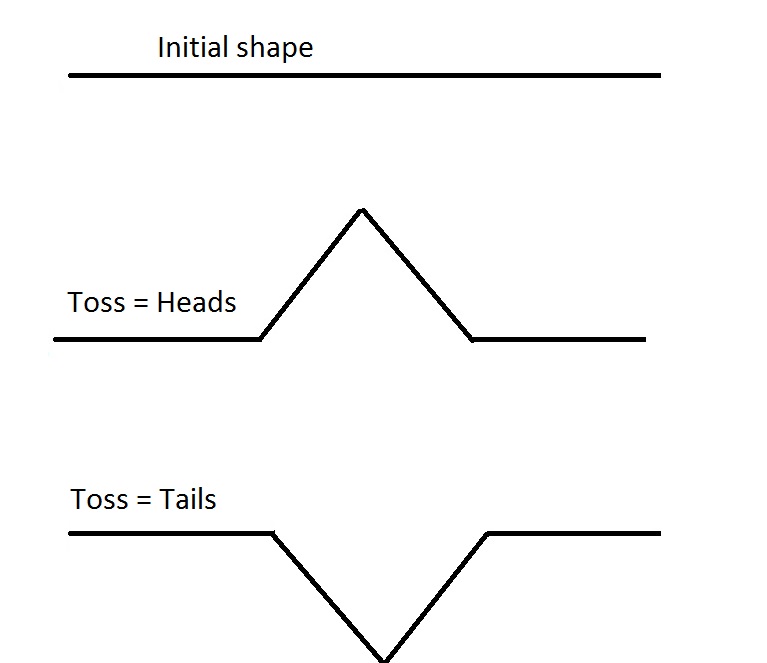
This is not just a question of how I spend my time but how I see myself, my identity. Day-to-day my identity may be relatively stable, but over the course of years it will change, my life-vector will keep on moving through this multi-dimensional space that defines who I am. The only guarantee for your vector is that it’ll keep moving as life keeps moving. I can plan for directions my identity will go, but it’s also at the whim of chance (e.g. I plan to dedicate my life to rock climbing, but I get a bad shoulder injury and have to give it up)

Throughout life dimensions will unfold and fold back in on themselves. At one point I played rugby, so one of the dimensions of my identity was as a rugby player, but I haven’t done that in over 15 years so that dimension has disappeared from my life and my identity. Conversely I’m not a father, so I have no identity along that dimension, but if I were to become one that dimension would unfold and become part of who I am, and I can choose how much of my identity is defined by being a parent.

How and why dimensions fold and unfold is for another post, but on a fundamental level it is a creative process – a becoming that starts in the unconscious and eventually rises to the surface of the conscious.

Don’t reduce yourself to a few dimensions

The constant flux of your identity within all these dimensions is completely subjective, so there’s very little objective advice to give about the process. However one thing I would say is that having a multidimensional identity is part of what makes us human, and to embrace the things that make us human is to affirm life.

Therefore reducing your identity to a few dimensions is exactly that: a reduction. If I only think of myself as a rock climber and all my thinking is tinged through the prism of rock climbing I am not living up to my potential as a person (because I’m reducing my personality down to one dimension when it naturally wants to have many).

A more common example is people who define themselves by a political ideology. If they think of themselves as a conservative or liberal first, and their opinions and thoughts are only formed in relation to that, they are reducing themselves as a person, they are denying (rather than affirming) themselves of a full identity (think about the difference between the thought processes: ‘I’m a liberal, what do liberals think of this?’ and ‘what do I think of this?’). This is what Deleuze means when he says ‘To affirm is not to bear, carry, or harness oneself to that which exists, but on the contrary to unburden, unharness, and set free that which lives’.

Nietzsche also sums it up beautifully: “No one can build you the bridge on which you, and only you, must cross the river of life. There may be countless trails and bridges and demigods who would gladly carry you across; but only at the price of pawning and forgoing yourself. There is one path in the world that none can walk but you. Where does it lead? Don’t ask, walk!”

Prune your Eigenvectors

There are only so many dimensions that a person can have in their identity. The exact number varies from person to person and also varies within a lifetime. Small children only have the capacity to define themselves along a few dimensions, but when you reach full maturity you have the capacity for many more.

The number of dimensions each person has the capacity for (and the magnitude of your life-vector) could be thought of as analogous to willpower. It’s a deep, constantly changing internal force that’s a complex amalgamation of nature and nurture.

Given that your identity has a limited capacity for how many dimensions it can carry, it is useful to continually check in on these dimensions and prune them if needs be. If there are dimensions (or eigenvectors) where you life-vector is barely above zero (small eigenvalues), do yourself a favor and get rid of them. It allows you free up the capacity to welcome new dimensions into your life.

Again, Nietzsche puts it well “What is life? Life – that is: continually shedding something that wants to die. Life – that is: being cruel and inexorable against everything about us that is growing old and weak”

Letting go of the parts of your identity that are dying can be a daunting process. One of the reasons why is that letting go is a conscious process, but creating new dimensions starts as an unconscious process – so you need to have faith in your unconscious. Letting go is the direction of strength.

In the past I used to define part of my identity as being knowledgeable and up-to-date with foreign policy and international relations. I spent a significant part of my time reading up about the endemic long term interests of different nations and how they interplay with one another, and would then avidly read the news through this framework. Over time that interest waned, but I still kept the pilot light on. The magnitude of my life-vector in the ‘International Relations’ dimension had decreased and was hovering just above zero. At a certain point I had the conscious thought ‘I need to drop this, I am now someone that doesn’t care about international relations’ – I let go of this dimension as it wanted to die. This freed me up to pursue new interests, and define myself in new ways, that I didn’t have the capacity for before.

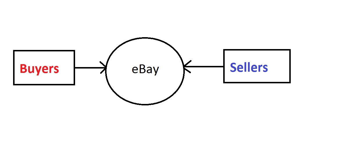
Dimension Reduction and interacting with other people

Where your life-vector is in relation to the dimensions you inhabit is entirely subjective – it’s pretty much the definition of subjectivity. You cannot fully comprehend someone else’s dimensions and life-vector – that’s life!

This is where dimension reduction comes in. You only see a projection of someone’s identity, a reduced dimensional map of them. The more you get to know someone the closer you get to comprehending all of their dimensions, but you’ll never get the full picture, even with your spouse.

For instance, if I meet someone at the climbing wall the first thing we’ll probably talk about is climbing. They’ll see (and assess) my identity through the lens of a climber. This may be the only level that we ever interact on, in which case they’re seeing my personality reduced down to one dimension.

Let’s say that it turns out they’re also into cooking, then we’ll also interact along that dimension too. They’ll get a more complete view of my identity, but it’ll still only be a 2D projection of my multi-dimensional identity. If I never divulge to this person that I’m a data scientist, they’ll have no idea about that side of my identity, how my relationship with data science has ebbed and flowed over the years, because that dimension is not part of the projection that they’re interacting with:

At 14.34 in the video below Deleuze says: ‘One has encounters with things, not people…. One encounters those elements – the charm people have, their work, not the people in and of themselves. I don’t give a damn about people, none at all.’

To me this dimension reduction analogy is what he’s talking about. You can never have an encounter with the totality of a person – just a projection of them.

David Foster Wallace also puts it nicely: “Inside you is this enormous room full of what seems like everything in the whole universe at one time or another and yet the only parts that get out have to somehow squeeze out through one of those tiny keyholes you see under the knob in older doors. As if we are all trying to see each other through these tiny keyholes.”

Dimensions are subjective

What makes interacting with other people complicated (even for non-Engineers!) is that our dimensions are subjective. My idea of what it means to be a data scientist is very different to what Tim Cook thinks it means to be a data scientist which is very different to what an 80 year old retired English teacher thinks it means to be a data scientist and so on.

So when people see a projection of me as a data scientist, there’s a very good chance our axes are not aligned. Their axes are rotated and transposed in relation to mine.

This happens all the time with political identities. Let’s say I’m a liberal, I have my own idea of what it means to be a liberal (supporting those in need, being compassionate, striving for equality etc.) and define myself along that dimension. But when I meet a conservative and tell them I’m a liberal they’re viewing me through their dimension of what a liberal is (hippie, ideology over community, breaking down societal norms for no good reason etc.). So the dimensions that they’re viewing my projected personality through are completely misaligned with how I think I’m coming across to them. This inevitably leads to misunderstandings, strawman arguments and miscommunications.

If you meet someone who has some of their axes totally aligned with yours there is a deep joy to be found – it confirms your world view (e.g. someone with your exact sense of humor). The fact that this joy is a rare shows that the the majority of interactions start with a misalignment of dimensions.

One could say that being diplomatic is being flexible with your dimensions – allowing your dimensions to rotate and transpose to meet other people’s. On the flip side being dogmatic is being rigid with your dimensions – forcing people to align their dimensions with yours. Engaging in a dialectic is to meet somewhere in the middle.

There are no universal dimensions

The other side of all dimensions being subjective is that there are no universal dimensions that everyone shares.

Taking this line of reasoning to it’s conclusion can degrade some pretty core concepts. For instance most people like to think of themselves as truthful, they have a dimension to their personality that says ‘I’m someone who strives to tell the truth and I value people who do the same’. But the truth-dimension is not the same for everyone, it’s a subjective concept rather than an objective one. There isn’t an underlying ‘truth’ in the world that you’re aligning your truth-dimension to, it’s all in your head.

Nietzsche: ‘What then is truth? A movable host of metaphors, metonymies, and anthropomorphisms: in short, a sum of human relations which have been poetically and rhetorically intensified, transferred, and embellished, and which, after long usage, seem to a people to be fixed, canonical, and binding. Truths are illusions which we have forgotten they are illusions’

Does this thought pattern descend into pure nihilism? Does it mean nothing really matters and life is pointless? No, not really. It’s a conclusion that you can make, but only if you’re predisposed to think that way. Shedding the idea of universal, shared dimensions is freeing. It allows you to appreciate each life-vector as it’s own singularity, all unique and to be appreciated from different projections.

At 0.40 in the video below Deleuze encompasses this idea concisely:

https://www.youtube.com/watch?v=5YXNofxbUz0
‘If one looks at a formula such as, All bodies fall, what is important is not that all bodies fall. What is important is the fall, and the singularities of the fall.’

It’s not that apples fall from trees, what important is each instance of each apple falling from a tree. When you untether your thoughts from relying on universal concepts the world goes from shades of grey to a kaleidoscope of color. The world (including your mind) doesn’t fit into neat conceptual boxes, so stop trying to swim against the current and go with the flow. Be an apple and enjoy your fall from the tree, it only happens once!

Conclusion

Thanks for making it this far! You may be the only one…

While I still love data science, these types of ideas take up much more of my mental energy these days. I don’t have much experience writing about philosophy, and I’m not sure if this just comes across as the mad ramblings of someone who’s been inside too much since March 2020, but I had fun writing it!

birth-life-death
checkdetector
http://georgemdallas.wordpress.com/?p=821
Extensions
Chaos theory, non linear dynamics and peripheries of maths: Part 1 – Back to basics
Uncategorized
‘The periphery of the circle of science has an infinite number of points, and while there is no telling how this circle can ever be completely measured, the noble person, before the middle of his life, inevitably comes into contact with those extreme points of the periphery where he stares at the inexplicable. When he […]
Show full content

‘The periphery of the circle of science has an infinite number of points, and while there is no telling how this circle can ever be completely measured, the noble person, before the middle of his life, inevitably comes into contact with those extreme points of the periphery where he stares at the inexplicable. When he here sees to his dismay how logic coils round itself at these limits and finally bites its own tail…’

Nietzsche, The Birth of Tragedy

Chaos theory, like relativity or quantum physics, enjoys a reputation that precedes itself. There are countless pop culture references to it (the film ‘The Butterfly Effect’ starring Ashton Kutcher being a particularly notable one) and it sounds cool and mysterious. It’s also quite easy to understand conceptually, the classic example being if you went back in a time machine and stepped on an ancient bug and came back to the present day the world would look very different. 

But if you think for a minute about the butterfly effect or the squished primordial bug it seems to contradict any predictive abilities we have in maths. If something so small and insignificant changes things so unpredictably, how can we predict anything? Are these examples overblown? If I stepped on a bug when I walked out of the time machine things will surely look mostly the same when I come back, with maybe a tiny difference?

No! These examples are actually accurate and the daunting truth is that most situations are too unpredictable for maths to handle. That dead bug really would change the course of history. The butterfly really could cause a tornado.

We think we’re good at seeing into the future because we can predict how man made systems (like machines or experiments) which are designed to be predictable, will behave in the future. But that is a testament to good design, not predictive power. It’s like saying you’re a talented artist because you’re good at colouring books. When we hold up our predictive tools, which have been honed over centuries, to the real world we fall laughably short. For instance one of the most studied systems in human history is the solar system. We know exactly how 9 planets and the Sun interact with one another. So we can model and predict where these planets will be for the rest of time (barring an outside event), right? Nope. We have a good idea what’s going to happen for the next 5 million years, but beyond that? We can’t tell. In relation to the age of the universe this horizon is not impressive. We’re at the mercy of chaotic systems, and they’re all around us.

The reason I’m writing this blog is because if you scratch below the surface of chaos you can gain a much deeper appreciation of it, and this appreciation can make you view the world differently. With high school maths knowledge you can see how maths breaks down and frays at the edges. It is humbling, as it shows us that we are not enlightened masters of our environment. Instead we drift in the dark sea of chaos, illuminated by our flickering torch of maths, trying to figure out where the next wave will come from. 

This post is written for someone who wants to approach chaos from the ground up, without getting too bogged down in maths. While there is maths in this post, I’ve made it as simple as possible and much of it you can skim over while still getting the point (though I do recommend trying to follow along).

There is quite a bit to get through so I’ve split this post into 2 parts. This first part is a rundown of dynamical systems, linearity and introduces the phase plane. It’s an overview of the types of system we can predict using maths. This recap of the mass spring system is the basics we need to cover before we journey to the limits – and hopefully it makes you see this physics problem in a new light.

To get the most out of this post, you should know about differentiation, especially over time (velocity and acceleration), e, sin and cos.

Dynamics and solving linear systems

Chaos theory is an area of dynamics, which is concerned with things that move, for instance a ball on a hilly surface. In dynamics we analyse systems, which is the mathematical model of everything going on with the things that move in the real world.

Because dynamics studies movement we deal with derivatives, mostly velocity and acceleration. A lot of dynamics is solving equations that relate position, velocity and acceleration to one another (how does the acceleration and velocity of the ball change at different positions on the hill?). The position, velocity and acceleration of an object in a model is its state. The state of a system changes over time because things move.

This is all a bit abstract so let’s look at the classic school physics problem, the mass and spring:

The spring with the weight on the end is the system we’re analysing. The arrow with x=0 shows the spring is at its resting point. If you dust off the cobwebs on balancing forces you may remember the equation for this system is:

This is the mathematical model of the system, which is pretty simple. It is an equation that relates the position of the weight (x) to its acceleration (x’’). It relates position to a derivative of itself. These are called differential equations and they are the bread and butter of dynamics. The goal is to solve these equations for a system so that we can say ‘where will the weight be at some point in the future?’. I.e. an equation that takes in time and spits out position. Once we have that we have solved the system, which is the ultimate goal.

Luckily for us differential equations are pretty easy to solve, as long as they’re linear. What does linear mean? It means that if we put the differential equation on a graph it’d be a straight line. Look at the spring equation again:

The spring constant k and the mass m don’t change, so -k/m is a constant number. A graph of x’’ against x looks like this:

See how it’s a straight line? That means it’s a linear equation. If the graph isn’t a straight line it’s non linear.

Linear differential equations are easy to solve because of e. E has the great property that it differentiates to itself and brings down the value not differentiated:

This property makes e the key to solving linear differential equations. For instance in the spring equation if we assume that x takes the form eat we can solve it quick (remember acceleration is position differentiated twice):

This image has an empty alt attribute; its file name is ql_a3a738a95fb31b556591d8b80dbd451d_l3.png

Subbing for a:

Easy! This is now solved and we have an equation where we can put in a time (t) and it gives us back the position of the mass (x). We call this an analytical solution to a system and once we have this we can predict what will happen to the system in the future for the rest of time.

People with more advanced maths will recognise the analytical solution for x in the spring to be Euler’s formula:

We can ignore the imaginary sin part here, making the less intimidating solution:

Which is easy to digest. The gif below shows how position changes over time:

A perfect cosine wave. Ignore the weight on the right for now, as we haven’t taken dampening or friction into account. The weight will oscillate back and forth, reaching an equal distance away from its resting point every oscillation. This is what we set out for in the beginning, an equation that takes in time and gives us back position.

But why did x need to be in the form eat? It didn’t. If you could find a version of x that satisfied the equation:

This image has an empty alt attribute; its file name is ql_a3a738a95fb31b556591d8b80dbd451d_l3.png

It would be a valid solution to the system. There’s no general methodological way of solving differential equations. It boils down to taking a guess at what x is and then seeing if it satisfies all the system’s equations. This is why the system’s equations are sometimes called constraints – before equations are introduced x could be anything, but the moment you start adding differential equations it constrains what x could be. For linear systems it just so happens we’ve done the guesswork already so we know the form that x will take ahead of time.

The fact that solving differential equations comes down to guesswork should start ringing alarm bells. Maths works best when there’s methodology behind solutions, it’s not so great at just guessing them. It’s also quite disappointing. How are the best minds in maths unable to solve such simple equations without guesswork?

Phase planes

Before we leave the mass-spring system I want to introduce a useful visualisation that’s used in dynamics called the phase plane. It sounds fancy, but it’s just a graph of how different states of the system move over time.

Often a phase plane shows position (x) against velocity (x’). What we plot on a phase plane is the trajectory of these two states over time, starting from an initial position. You need to follow the direction of the lines to see how the states evolve over time. We know already that:

This image has an empty alt attribute; its file name is ql_62e426a4af692a05838d650e05860d5b_l3.png

The speed of the ball is just x differentiated with time, which is:

So as time increases the x axis is cos and the y axis is -sin, so the result is an oval (or circle, depending on how you scale the axes) that goes clockwise with time, like below:

There’s a couple of points to mention here:

  • The graph above shows 2 different trajectories for the mass spring system. The mass on the outer circle starts further away from the resting point than the mass on the inner circle. It has more energy.
  • These are perfect circles because we’re modelling perpetual motion. There is no friction in our model so if our weight starts a certain distance from the resting point it’ll keep returning there because it doesn’t lose any energy. This leads to the closed loops in the diagram above.

The diagram below shows where the mass spring system is at different points on the circles. Notice where the mass is in relation to the resting point

For completeness sake here’s how time relates to x and x’ at certain points on the trajectory:

Any other trajectories would look similar to the ones above. A circle/oval with a radius that’s dependant on how much energy the system initially starts with (the further out you pull the mass, the more energy you’re giving the system, the bigger the circle on the phase plane).

While phase planes are not used that much for linear systems, they become an indispensable tool when we start to look at non linear systems, as it helps to visualise how the system evolves over time in different scenarios.

So far we’ve been studying a perpetual motion machine. This is because when we modelled the system with maths we didn’t take into account friction or anything that could take energy out the system. Obviously in the real world this doesn’t exist. Lets look at the gif above again, but this time focus on the right hand side:

This image has an empty alt attribute; its file name is W9512PjfrHHbjdgLUHyKz6fy3WRXnThdrdX695DdZtxh2m3eOP3cgOZgru6wnYRIH5jizbseIphBQ2kjgjetOEc2F8b-ARfXTZkNNRjmdR6zh2N26L4R4WyBUyU1eKza4cchqwRV

In the real world we release the mass, it oscillates around its resting point, but gradually loses energy so that after some time it returns to its resting position. I won’t go through the maths here, but even without the maths you should intuitively be able to sketch out what the phase plane would look like for such a trajectory:

Now we see what real world phase planes look like. Notice how this trajectory isn’t a closed loop like before. Instead when the mass is released from it’s initial position it loses energy, so that it won’t quite return to it’s original position after 1 oscillation. Instead we gradually spiral to the resting point, where position, velocity and acceleration are 0. In dynamics we call this resting point an equilibrium. The equilibrium in a mass spring system is called a stable equilibrium because all trajectories will eventually end up there. Wherever you start from the mass will eventually end up in its resting point. The term ‘stable equilibrium’ implies the existence of an ‘unstable equilibrium’, but I’ll go over that in the next post.

Conclusion

This post has shown how we can use dynamics to find the solution to linear systems. When a system is linear, like the mass spring, we can apply lots of analytical tools to dissect the problem and deeply understand what’s going on. When I said in the introduction that we are good at predicting things designed to be predicted this is what I was referring to: linear systems.

In engineering we strive to make dynamic systems linear because they’re easy to analyse. We design systems with linearity at the forefront of our minds. If part of the system isn’t linear, we linearize it so that we can analyse it. Linearizing means you find a part of a non linear function that looks straight, and then pretend that it is linear. We do this because, as you will read in the next blog post, our analytical capabilities start breaking down with non linear systems. If we run into non linear differential equations we desperately try and make them linear in whatever way we can, because that’s what we know.

Now that we’ve covered the basics of how maths can help us dissect a linear man made system, we can begin looking at how maths stutters when confronted with non linear real world systems. This will be the subject of the next post, along with how chaos theory plays into all of this and what chaos looks like mathematically.

mass-spring-phase-plane-with-friction-1-3
checkdetector
This image has an empty alt attribute; its file name is ql_a3a738a95fb31b556591d8b80dbd451d_l3.png
http://georgemdallas.wordpress.com/?p=769
Extensions
The Story of Computer Vision
Uncategorized
What is computer vision? Where has it come from? 20 years ago only a few esoteric Engineers were working on it, but now mass-market products like the Microsoft Kinect, Google’s driverless cars and facial recognition systems are using computer vision in a fast, cheap and effective way. What happened? One reason is that computer vision […]
Show full content

What is computer vision? Where has it come from? 20 years ago only a few esoteric Engineers were working on it, but now mass-market products like the Microsoft Kinect, Google’s driverless cars and facial recognition systems are using computer vision in a fast, cheap and effective way. What happened?

One reason is that computer vision requires a lot of processing, and computers have only recently become fast enough to handle the workload needed. However this is not the only reason why computer vision has gone from an academic dream to a consumer reality.

The main reason is that about 10 years ago Engineers started incorporating machine learning into computer vision and subsequently revolutionized the field. Before machine learning, scholars set themselves incredibly hard mathematical problems in order to get a computer to recognise objects in an image. After machine learning was introduced these tasks became trivial, becoming a matter of simply training a computer to learn what objects look like. This freed academics from the mathematical black hole they were in and allowed them to pursue more interesting problems in the field.

This blog post tells the story of computer vision, explaining why the introduction of machine learning was so significant. It starts by explaining the main objectives of computer vision and why object recognition is a fundamental goal. It goes on to show why this is a complicated problem and how Engineers initially went about tackling it. It ends by describing how machine learning is used to make these previously arduous challenges much quicker and easier.

I specialized in computer vision at university, spending a year studying it. This post is somewhat of an ode to the field, as I have an affinity towards it. Only basic maths knowledge is needed to understand it.

An Engineer’s Problem

The difference between science and engineering is their objectives:

The role of science is to discover the truth about the world. It tries to explain natural phenomena that occurs. If a scientist can correctly predict how natural events happen using the scientific method (reason, logic, maths) they are doing their job.

The role of Engineering is to provide people with what they need and want. It uses the scientific method to create products that do what people want them to do. If an Engineer can produce a product that people want, they are doing their job.

Computer vision is based on an intuitive want, namely ‘I want a computer to be able see images like humans see them”. Therefore it is fundamentally an Engineering problem. If we can satisfy this want we have done our jobs.

While this goal may be an obvious one to pursue, it is not so obvious how to approach it. The first question that arises is ‘what exactly about human vision do we want a computer to do?’. We don’t yet really know what happens when you ‘see’ something. For instance when you see a car coming towards you, how does your brain recognise the car, realise it’s coming towards you, and then process this information to make your body move out of the way? Neuroscience is not (yet) much use here. However if we don’t know how humans process what they’re seeing, how are we going to get a computer to do it?

The way that Engineers have approached this huge task is by breaking it into smaller, more manageable problems. Let’s think about that car again. First, before you can react, you need to recognise your surroundings. You need to identify the car, the road, the pavement and other things. Once you have done that you can start to figure out how fast the car is going, that it’s approaching you and that you should move out of the way. The same is true for almost any situation, before you can figure out whats going on or how to act you need to know what you are looking at. Therefore it makes sense that before computers can start doing anything useful with the images they get, they need to recognise what’s in the image.

Making a computer recognise objects in images, or object recognition, is the first major hurdle to overcome in computer vision. Once this is effective we can start to make a computer try and ‘understand’ the images by seeing how the objects relate to each other, how they’re moving, what actions to take and so on. However while object recognition is only the first hurdle in computer vision, it stumped academics for over 30 years. To understand why it’s worth considering what a monster of a problem object recognition is.

Object Recognition

Let’s have a think about what we mean by object recognition. Say we want to get a computer to recognise a human in an image. The computer would be given an image and we want it to decide whether the image has a human in it, and where that human is in the image. Like this:
biker

So how do we go about making this happen? First thing to to is appreciate the environment we are working in with this problem. What data does the computer get? How does this data relate to the real world?

The Data

The data the computer gets is an image. Images are made up of pixels, tiny dots on the screen that can be any color. An image that is 1024 x 768 has 1024 x 768 pixels, or 786,432 pixels. Each one of these pixels is a bit of data that needs to be processed. This sounds like a lot of data, but there’s more…

A pixel actually consists of 3 small LED lights that are red, green and blue. These three LEDs shine at different intensities in order to create the colors on the spectrum. So each pixel has 3 color values associated with it, how intense the red, green and blue LEDs are.

Not only that, but each pixel has a location in the image. This is represented by 2 numbers (x,y) showing where in the image the pixel is.

Therefore there are 5 variables associated with each pixel (2 for location, 3 for color). This means that in a 1024 x 768 image, there are (786,432 x 5 =) 3,932,160 bit of data! This is a huge amount of data to process, even for Engineers. It’s also extremely daunting: within almost a million pixels you need to find the pixels where a human is, and discard the rest.

While the amount of data to deal with is definitely a challenge (especially video, where you get 24 images a second!), it is not the main problem. The main problem is how images relate to the real world.

An image is a way to measure the world. However it is a 2D measurement of a 3D world. Take a look at this:

compvis1

This is representation of the light that an image collects when a camera takes a picture. X1 X2 X3 and X4 are points in the real world and x1 x2 and x3 are their projections on the image.

As you are probably already aware, a picture is 2D. You can print a picture on a piece of paper. However the world we live in is 3D. Therefore when we take a picture we lose a dimension, namely depth. In the picture above you can see that the photo captures the x and y dimensions, but not the z.

This is a problem for Engineers because when you lose a dimension you lose information about the real world. Information that is hard to get back. This problem is best seen by looking at X1 and X2 in the picture above. In the real world X1 and X2 are far away from each other, however in the photograph they are very close to each other. The reason for this is because X1 and X2 are far away from each other along the z axis, depth, which the image can’t capture. Therefore they look close to each other in the image even though they’re far away.

Another problem with photos only capturing 2 dimensions of a 3D world is occlusion, or objects blocking one another. In the photo above you can see that X3 and X4 are both being projected onto the same point. Because X3 is nearer to the camera, it will block X4 so that it will not be visible in the photograph.

So we need to process a huge amount of data that contains incomplete information about the real world. This is not pleasing. In general we like to deal with a small amount of data that accurately measures the world. Therefore before we even approach object recognition we know we have our work cut out for us.

The Method

Let’s return to the problem at hand, object recognition. Say that instead of a human, we want a computer to recognise something much simpler in an image. An orange

orange

The method that gets a computer to do object recognition is called template matching. Template matching uses a ‘template’, or model, of the object we want to find (in probability parlance this is called a prior), and then scans an image to see if any part of it is similar to the template. In the picture below you can see our template of what an orange looks like (an orange circle), and which part of the image looks most like our template after scanning it:

orange template

The technical name for scanning the image with a template is called cross correlation. Cross correlation compares two sets of data and returns a measure of how similar they are. If the two sets of data are the same the cross correlation is 1, if they are completely different the cross correlation is 0.

To visualise scanning the image, imagine that we are moving the circle around the whole image and looking at the data inside it. If the cross correlation with the template is high, the computer then thinks an orange is there. If it’s low then the computer ignores it.

correlation

So after we have a template we can just scan an image and make a rule like ‘if the cross correlation with our template is above 0.8, then it’s an orange’. If no part of the image has a cross correlation above 0.8 then the we simply say that there isn’t an orange in the image.

That’s the basics of template matching. Seems pretty simple right? Make a model of something and see if any part of the image looks like it. How did researchers hit a brick wall if that’s all there is to it?

Templates – the crux of the problem

When we make a template of an object, it needs to be a representation of what an object will look like in a picture. It therefore needs to be in 2D, because we are comparing it to a 2D picture.

However this leads to significant problems because objects in the real world are 3D, and creating 2D representations of them is tricky business.

The example of the orange hid this nicely, because an orange is unique in how simple the template is to make. Think about it: any way you look at an orange (and in almost any lighting) it will appear in a 2D picture as a orange circle. For every object we want to detect that isn’t an orange, the problem of making these 2D templates becomes very hard very fast.

For instance lets think about how to make a template of a cube. When a photograph of a cube is taken, the cube can be in any orientation. Take a look at the gif below of some of the ways a cube could appear in a photo (borrowed from this website)

roatating cube

As you can see, there are many different ways that a cube can appear (imagine it rotating up and down as well as left and right). Yet if we want to find any cube that appears in an image, we need to make a template of each orientation. This is because if we had templates of only a few orientations, when we template match we will only be able to find a cube in those specific orientations. In order to detect a cube at any orientation, we need a template of every way a cube can appear in an image.

Let’s say we had 100 templates of the different ways a cube can look in an image. To detect a cube, we would then have to do template detection on each of these 100 templates, and if at any point in the image any of the templates had a high cross correlation the computer would detect a cube.

Hopefully you can start to see how templates became a big issue for researchers. Objects like humans are much more complex than cubes, and if we want a computer to detect them we need templates that can account for all the ways you can position your limbs, all the angles the photo can be taken from, as well as accounting for all the different shapes, sizes and skin tones of people. You need thousands of templates to detect a human, and quite a bit of imagination!

Initial Attempts

Now that we have seen how making templates is at the heart of object recognition and that they are difficult to create, we can start to see the brick wall that researchers hit. Hundreds of papers have been dedicated to creating good templates, but a large proportion of them could not recognise objects reliably. This is because if the templates were anything less than perfect, template matching would not work properly.

Bad templates can lead to two problems. First of all if your templates don’t accurately represent the object you want to find, it is likely that the computer won’t find that object in an image, even when it’s there. If this problem occurs we know that we should try and create a template that more accurately represents the object at hand. The second problem is that your template might produce ‘false positives’ – or think that it has found an object in an image even when it isn’t there. If this happens then we probably need to simplify the template so that it doesn’t think random bits of an image are objects.

Making templates is therefore a balancing act – you want to be able to encompass all the unique features of an object, but you don’t want to be over-accurate or else you’ll get false positives. A quick example to highlight what we mean by over-accurate: say you want to make templates of humans, but all your test subjects happened to be wearing red t-shirts. If you incorporated a red t-shirt into your template of a human the computer will start looking for red in an image, and if it finds any red it’ll think that a human is likely to be there. However this isn’t the case, humans can wear any color t-shirt. Using red in your template is being too accurate on your test subjects – giving the computer an excuse to find humans in an image where there aren’t any.

Researchers initially tried to make templates by making mathematical models of objects. For example when trying to model humans, researchers relied on models of humans as stick men. The picture below is a random selection of how humans have been modeled in various papers.

bodies

While these representations may seem a bit simple and silly, they make sense. These templates can’t be too complex (or else they get false positives) but need to capture all the features of humans that make them appear uniquely ‘human’. Therefore making stick men to use as templates isn’t a bad place to start, as most people have the same body shape as a stick man. However this isn’t good enough to recognise humans.

The reason why is because mathematical modelling always makes assumptions about the world. Assumptions that aren’t necessarily true in the case of computer vision. For instance when using stick men as templates we are assuming that humans have the same rough shape as a stick man and will always appear in an image as one. This isn’t true in real life. People vary hugely in weight, some appearing more circular than straight, which the stick man doesn’t account for. Also people wear clothes that can conceal their body shape, for instance women wearing hijab. The stick man template will not detect these people in images because it assumes certain things about the way humans look a priori which are not universally true. When making a model, the assumptions made inevitably includes/excludes features that shouldn’t be there.

Another problem with the template of a stickman is that there are many different ways that a stickman can contort itself, some contortions being more likely to occur than others. For instance look at these two different stickman poses:

stickman

The template of the stickman on the left is likely to occur in images, as people pose like that all the time. Therefore it is a good template to use when searching for humans. The template on the right is extremely unlikely to occur in images, as it is almost impossible to position your body in this way. Therefore this isn’t a useful template to use when searching for humans. If we were to include the bad template the computer would detect a human where there isn’t one – for instance some branches of a tree may look similar to the bad template, so the computer would identify it as a human.

So even if our stickman model of a human was really accurate, we would still need to define the likely and unlikely poses that it would take. This is a very hard task – how do you define all the likely poses a human could be in? Researchers again tried to put into maths likely human poses. But this is a long, hard and fruitless task. You can’t model likely human poses without making dodgy assumptions that ultimately lead to bad object recognition. For instance one research paper modeled limbs as ‘springs’ so the more you bent your limbs the more unlikely the pose was. This is a bad assumption because it is patently not true in real life – bent arms is not an unusual pose. However this kind of mathematical modelling was the norm in object recognition for quite some time.

The challenge Engineers set themselves was therefore huge. If you wanted to get a computer to recognise something you had to mathematically define what the object looks like at every angle and how it would appear in the real world. This put research in a rut. Papers that claimed to recognise objects accurately only did so in very specific conditions (e.g. some papers could detect humans only if the background was completely black), While other papers filled pages with equations of how objects could appear that ultimately didn’t lead anywhere – being either too simple (false negatives) or too complex (false positives).

Then machine learning was used to make templates and changed the approach completely.

Machine Learning

Machine learning is a field of Information Engineering that developed completely separately from computer vision. Put simply, machine learning is a way of classifying new data based on old data. Take a look at the picture below (from a previous blog post on machine learning)

ml4

Here is a graph of various student’s IQs and test scores. They are classified as going on to earn either above or below 30k a year – the red circles being above 30k, the blue squares being below 30k. This is our ‘old’ data, data we have already collected about students. When we get a new student’s test score and IQ, we can then look at this graph and predict whether they will earn above 30k or not. The student can be classified as above/below 30k because we already have data on past students.

Machine learning makes a computer automatically do this classification rather than a human. Let’s say instead of IQ and test score, we had 10 variables on each student like weight, gender, family income etc. as well as whether they earn above or below 30k. When we get a new student’s information, we cannot simply look at a graph and classify them as above/below 30k, because you can’t plot a graph with 10 dimensions. However if we give a computer enough information on past students, it will be able to take the new student’s information and classify them as above/below 30k. The computer can do this even if we have loads of variables about each student.

Machine learning is useful because after you have ‘trained’ a computer by giving it lots of old data, it will start classifying new data by itself. The computer will automatically look for old data that is similar to the new data, and classify it accordingly (e.g. in the picture above, if the new student has a high IQ and test score, the computer will see that other students with high IQ and test scores earn above 30k, so the new student will be classified as above 30k). Once you have trained the computer, you can sit back and relax while it classifies your new data. The computer program that does this classification is called (unsurprisingly) a classifier.

Classifiers are also fast. Once a computer is trained it can classify new data in a very efficient manner.

So what does machine learning and classification have to do with making templates? This is where the truly elegant insight comes in. If you think about it, when we are trying to recognise a human in an image we are classifying the pixels as either human/non-human. Our template of a human is essentially a classifier, telling the computer ‘here is what a human looks like in an image, everything that doesn’t look like this isn’t a human’. Humans are red circles, non-humans are blue squares.

When researchers were making templates with mathematical models, they were making classifiers based purely on their thought an not on past data. They were relying on their insight to draw lines of distinction in a dizzying set of over 3 million data points. As we have seen this was a profound task that would make even the most confident Engineer whince. What they didn’t realise is instead of conjuring up in their minds what a human looks like, machine learning could learn from past images what a human looks like, and automatically do this process of classification for them.

Here’s how it works. You collect a load of images with people in them. This is your old data to train the classifier. You then mark out in each image where the person is and then give this to the computer. This is your way of classifying pixels in an image as human or non-human, red circles or blue squares. Like the picture below:

Ticino. Corippo. Alps. Mountain village. Landscape. Environment. Biker.

Once you have fed thousands of pictures that have been classified as human/non-human, the classifier will learn which sets of pixels in an image are likely to contain a human in them and which are not. This means that our trained classifier will be able to take a new picture, look at all the past pictures it has which are similar to it, and determine whether or not there is a human in it.

There are three huge benefits in doing this:

– You can give the computer pictures of people in different clothing, lighting, shapes, sizes, skin tones and so on. The computer will then determine what attributes are common across all humans and which are not (like red shirts aren’t important but general shape is). It is able to pick out subtleties that distinguish a human which an Engineer can’t.

– It drastically decreases the workload for the Engineer. Now making templates is simply a matter of giving a computer images that have been classified, which is so much easier than the previous task of modelling.

– It’s fast. Previously when you had hundreds of templates for something (remember the cube) you had to scan each template over each part of the image to see if you had a match. This takes a long time, even on modern computers. With machine learning you can find an object much quicker, as the computer just needs to see if the picture has any of the attributes of a human that it has already figured out.

I love this. It is a completely different way to approach object recognition and it has provided breathtaking results. To me this kind of insight is a mark of true genius as it makes a previously unsolvable problem trivial by incorporating a completely separate field.

From research to product

As you may have guessed from my examples, I specialised in human recognition. In this area the ultimate goal has been to get a ‘real-time’ 3D pose of a person from video i.e. when I dance infront of a camera I want a 3D stickman on screen copying my movements at the same time.

It was a few years after machine learning started being incorporated into human recognition that this goal started to be realised. Researchers had attempted to train classifiers with pictures of people but they weren’t very good. The reason why is quite interesting.

A classifier that can find humans needs to train on a huge amount of images. This is because humans are very complex objects, mainly due to the fact that we can position our limbs in different ways (think back to the stick men). So for a classifier to learn all the different ways a human can appear, it needs thousands and thousands of images to learn from, or else it may not recognise a certain pose. The reason that machine learning didn’t work for researchers initially is that they didn’t have the time or man power to train a classifier with so many images. The upfront grunt work was simply too much to handle in an academic setting.

Because of this, it was actually Microsoft that came out with the first system that is widely regarded as meeting this ultimate goal of human recognition: the Microsoft Kinect. Because Microsoft stood to profit from a good human classifier, they were willing to put in the money and time required to train one up. If I recall correctly the Kinect has been classified with over 100,000 images. This has led to a system which can track you in real time, allowing you to use your movements to control a game.

But the Kinect isn’t the end of it. Classifiers will come out that are trained on more images and are more accurate. And classifiers are yet to be trained on many other objects that would be useful to recognise. Thanks to machine learning computer vision has finally taken off the ground and is starting to realise the goal of making computer see images like humans do.

checkdetector
biker
compvis1
orange
orange template
correlation
roatating cube
bodies
stickman
ml4
http://georgemdallas.wordpress.com/?p=586
Extensions
An Engineer’s Guide to Cooking
Uncategorized
I have recently delved into the world of cooking. But as an Engineer simply following recipes doesn’t quite fill my appetite for culinary knowledge. What happens to food when it’s cooking? Why does a steak need to rest? What happens when something is ‘aged’? Most people want to learn how to make a good meal […]
Show full content

I have recently delved into the world of cooking. But as an Engineer simply following recipes doesn’t quite fill my appetite for culinary knowledge. What happens to food when it’s cooking? Why does a steak need to rest? What happens when something is ‘aged’? Most people want to learn how to make a good meal rather than the science behind it, so these sort of questions don’t often appear in recipe books. However Engineers aren’t most people…

Over the last 20 years there has been a big focus on the science of cooking and great literature has accompanied it. This short post is about the most important rule I have learnt so far: the temperature of the water inside the food is vital.

There are hundreds of lessons to be learnt about the science of cooking, but I find this one cruical because it applies to all cooking methods and almost all foods. The rule may seem simple, but don’t be deceived. Once you start focusing on internal rather than external termperature your approach to cooking adapts and your culinary knowledge inevitably broadens.

What cooks food?

We all know that cooking requires heating food up. Frying, boiling, steaming, roasting etc. are all ways of supplying heat to food. Let’s think about a steak on a frying pan:

food1

The frying pan is very hot and will obviously heat up the surface of the steak it is touching. But how does that heat move through the steak, so that the middle of it (which isn’t in contact with the heat) becomes medium rare or 55C/131f?

To answer that we need to know what a steak is made of. If you remember biology in school you’ll recall that all meat, fruit and vegetables are predominantly made up of water (steak is 75% water, potato is 80% water, tomato is 95% water). So how does the heat move through the steak? By heating up the water inside the steak. The water in the steak near the pan heats up first, which heats up the water around it, which heats up the water around that. Gradually the water at the centre of heats up to 55C/131f and we have a medium rare steak. In Engineering terms, the heat moves via conduction through the water particles in the food.

The first thing to realise is that way of heating don’t just apply to a steak in a pan, but applies to all techniques and almost all ingredients: an external heat source warms up the water inside the food. The second thing to realise is that the water inside the food is the thing that cooks the food, not the heat around the food. The heat around the food will cook the outer layer of the steak, making the brown crispy exterior, but the majority of the steak is cooked by the water inside.

Why is water temperature useful to think about?

So we know that the majority of cooking is done by the water inside the food, so what? How does this help? Well now that we have this fact under our belt we can start ascertaining interesting things about water and food, which will translate into practical use in the kitchen.

Boiling point

First thing to think about – water boils at 100C/212f. No matter how hot the surroundings are, the water inside food will never be over 100C/212f. For instance when you fry an onion, even though the pan can be 200C/392f, the temperature of the onion will not exceed 100C/212f.

I find this point to be illuminating. The temperature of food will not exceed 100C/212f, even if it is in an extremely hot oven. This means that the temperature range in which food can cook is relatively small – only between 40C/104f-100C/212f.

What if there is no moisture in the food? Lets continue with the onions in the pan. If the pan is very hot and is left to fry the onions, they will first leak their moisture into the pan, and eventually the moisture will boil off. Once all the moisture is gone the dry onion will then get hotter than 100C/212f and start approaching the temperature of the pan. However, apart from spices, pretty much all food has water in it and you won’t want to boil it off.

Leaking

The second thing to think about is how much moisture the food has in it. When you cook food it is inevitable that you will lose some of the water inside the raw ingredients. How much you lose depends on what you want to do. For instance when frying onions the moisture will leak into the pan, but the onion-y water combines with the fat to create a great flavour base for many dishes – so we want the moisture to leak. However in a steak we want to retain as much moisture as possible, so we try and leak as few juices as possible.

The amount of moisture that a food should retain depends on the recipe, but an important fact to keep in mind is that food with less moisture will cook quicker. This is basic physics. If I have two pots of water, 2 litres and 1 litre, and you give them the same amount of heat, the 1 litre pot will heat up quicker. The same goes for food. If you have a raw steak and a well done steak in the same pan, the well done steak will heat quicker because it has less water inside it.

The influence of the amount of water in food is best observed in baking. The main purpose of baking is to dry out ingredients with the convection of hot air. A notorious aspect of baking is that there is often a short time frame in which your food is cooked perfectly – 20 seconds too long and it’s overdone. The reason for this is to do with water content. When the water inside the ingredients gets hot enough to start evaporating, the ingredients start to lose water. This means that the food starts heating up faster as there is less water, which then makes more water evaporate, and so on. This runaway effect is the reason behind the short time frame, as once the food starts losing water it heats up quickly.

Evenness

The last thing to think about is that the temperature inside the food is never uniform. The side of the steak near the pan will be hotter than the middle of it. The skin of a roasting chicken will be hotter than the centre.

However we often want an ingredient to be a uniform teperature throughout. A perfect medium rare steak is 55C throughout, not just the middle. A rare duck breat is 53C/127f throughout, not 53C/127f in the middle and 70C/158f at the edge.

Acheiving a uniform temperature throughout the food is hard to do using conventional cooking methods, because the external heat is usually much hotter than the desired internal temperature of the food. If the pan is 200C/392f and you need the centre of the steak to be 55C/131f, there will inevitably be a bit of the steak between the pan and the middle that is above 55C/131f and therefore overdone.

Conclusion

Getting ingredients to be the correct temperature throughout, maintaining that temperature for the correct amount of time and retaining the correct amount of moisture are three fundamental aspects of cooking that need to be mastered in order to become a good chef. And all of these are related to the temperature of the water inside the food.

There are lots of practical tips that have come from thinking about the water temperature inside food. For instance you should flip a steak every 15 seconds rather than only once, because constant rotation allows the steak to graudally heat each side to 55C/131f and causes minimal leaking of moisture – resulting in a steak that is juicer and more evenly cooked than a steak flipped once. Another is that steaming or pan frying vegetables retains much more moisture than boiling them, resulting in vegetables that retain their taste. Yet another is that humidity fluctuation is the root cause of uneven baking, as humidity dictates how much moisture can evaporate and therefore the cooking time.

While there are plenty of tips to get from this information, I hope that this post has also opened your mind to the science behind cooking and deepened your understanding of something that you do everyday. The science of cooking isn’t only useful for Michelin star chefs, but also for anyone who cares about what they put in their mouth.

checkdetector
food1
http://georgemdallas.wordpress.com/?p=575
Extensions
Making sense of Internet Platforms: Network Effects and Two Sided Markets
Uncategorized
It seems like the quickest way to make a billion dollars at the moment is to create a successful internet platform. Companies like Facebook, eBay, Airbnb, Twitter and Paypal are platforms that have gone from obscurity to internet giants in a matter of years. So what are these platforms and how are they making so […]
Show full content

It seems like the quickest way to make a billion dollars at the moment is to create a successful internet platform. Companies like Facebook, eBay, Airbnb, Twitter and Paypal are platforms that have gone from obscurity to internet giants in a matter of years. So what are these platforms and how are they making so much money? A lot of starry-eyed tech entrepreneurs wax lyrical with theories that equate the technology revolution to a revolution in business and economics. But the typical way an internet platform makes profit is by acting as a two sided market, which is a type of business that existed long before the internet.

Two sided markets are naturally able to thrive at huge scales and platforms have been taking advantage of this, attaining unbelievable valuations. It is useful to view internet platforms through the lens of a two sided market because it explains the incentive structure of the platform and how the companies orient themselves in terms of product decisions.

This blog post first describes network effects, an economic concept that helps you understand two sided markets. It then goes on to describe the structure of a two sided market and who to incentivise within it. The post ends by showing how many internet companies have structured themselves around a two sided market principle. There is no maths in this post and the concepts discussed require no background knowledge.

Network effects

There are some products and services that become more valuable if more people are using them. For example think of e-mail. If there were only two people in the world who had e-mail, they would only be able to talk to each other and the service would not be very valuable. When a third person gets e-mail, the service becomes more valuable to the original two users as now they can contact someone else. When a fourth person gets e-mail, the other users find it more valuable as they can contact more people on it. Every time a new person gets e-mail, everyone already using e-mail benefits a bit more because they can talk to more people.

This phenomenon is called a network effect and it occurs in a large amount of internet services. When everyone uses the same product and they are all benefiting from doing so, it’s good news for whoever makes the product. Take Facebook as another example. I know a lot of people who want to delete their Facebook account but don’t because it is so easy to contact everyone they know on it. This is a network effect. So many people have Facebook that it is effectively a directory of people, making it a valuable service. Every time a new member joins Facebook everyone benefits a bit more. This value only exists because of the amount of people that use it and doesn’t have much to do with Facebook itself (you could try and contact people on Myspace, a service very similar to Facebook, but no-one uses it so it isn’t very valuable).

When there are multiple companies offering a product that has network effects, you can quite easily show that everyone benefits the most if they all use the same product. For instance if there were hundreds of social networks with only a few thousand people on each one, the users wouldn’t benefit as much as they would if they all used Facebook. This is because of the network effect.

This ‘all or nothing’ aspect of network effects can lead to some interesting market dynamics. When two products that rely on network effects are competing against each other, there will usually be a ‘tipping point’ where everyone suddenly starts banding together to buy one product, leaving the other product useless. A great example of this is the Bluray vs HD DVD saga.

Bluray and HD DVD are products that provide better quality video than DVDs and both rely on network effects. Bluray becomes more valuable if more people have Bluray, as you can then share movies and you can be sure that the newest releases will be in your format. The same goes for HD DVD. If everyone bands together around a common video format everyone benefits.

The graph below shows the pivotal week in the competition of Bluray vs HD DVD. In a week Bluray went from having a 51% market share to a 92% market share. This was the week that Warner Brothers announced it would support Bluray devices only, and not HD DVD. You can see that this was the ‘tipping point’: everyone decided to use Bluray and leave HD DVD to wither away.

platforms1

So we’ve seen how network effects are a quality of many internet products and that they can be vital in determining the success of a business. However network effects don’t only occur in certain types of product, there are also businesses that use network effects in their structure. Namely two sided markets.

Two Sided Markets

A two sided market is a business that brings two groups of people together. The structure is shown below:

platforms3

The most basic example of a two sided market is, quite literally, a marketplace. One group would be farmers or food sellers, the other group would be people who want to buy food. The marketplace is where the two groups meet. The business’ value is providing a space in which these two groups can interact and it makes money by charging farmers to have a stall in that space.

This structure is how most internet platforms make their money. They bring two groups of people together and charge one (or both) groups to do so. Lets take an example of an internet marketplace: eBay

platforms4

Just like a marketplace in real life, eBay provides a space where people who want to sell something and people who want to buy something can interact (through an auction). The way that eBay makes money is by charging the sellers whenever they list something, just like how farmers pay for a stall.

The network effects in two sided markets are slightly different to what I described above. In the examples above there is one group, the consumers of the product, who benefit when more people join their group i.e. when more people use the product. E-mail users benefit when more people use e-mail, Facebook users benefit when more people use Facebook. Like the diagram below:

platforms7

What is different in two sided markets is that Group A benefits when there are more people in Group B and vice versa. Members of Group A don’t really care how many people are in their group, they care about the other one. This is shown below:

platforms6

The way to get your head around this is by imagining that sellers on eBay only sold one product, say sofas. If there was 1 person selling a sofa and 10 people looking to buy a sofa, the seller will be happy because the buyers will probably aggressively bid and the seller will get a good price for it. Furthermore, if an extra person wants to buy a sofa, the seller is happier because he will contribute in bidding to a high price. Conversely if there was 1 person wanting to buy a sofa and 10 people selling, the buyer will be happy because the he can look for the cheapest sofa rather than having to compete with other buyers. If an extra person wants to sell a sofa the buyer is more happy because he might provide a better deal. The buyers benefit if there are more sellers, the sellers benefit if there are more buyers. This is the network effect in a two sided market [NOTE: each group does benefit if there are more people in it, but in an indirect way that I won’t describe].

We’ve seen how in a two sided market each group cares about how many people are in the other group. So how does a company like eBay use this information to their advantage? They use it to structure the incentives for each group, as the two relationships are usually not equal. This unequal balance of relationships is best highlighted by the classic way an internet platform makes money, the quarter pounder with cheese: connecting advertisers and consumers.

The Advertising Model

The way that Google, Facebook, Twitter, News websites, Hulu and more make the main bulk of their money is by connecting advertisers to consumers:

platforms8

All these services are two sided markets because they provide a space where consumers and advertisers can interact. However the relationship here is clearly skewed towards advertisers. If there are lots of consumers looking at the adverts then the advertisers are happy. When more consumers are in the market the advertisers get much happier, they therefore strongly benefit from the relationship. The consumers don’t get as good a deal. If there are more adverts available to be shown to you, there is an argument that the consumer would benefit from more targeted advertising, however it’s not that beneficial: on the whole people don’t like adverts.

Because the advertisers benefit from the relationship so much more than the consumers, it makes sense for the platform to incentivise the consumers with its products. Advertisers gain value from the relationship, whereas consumers don’t. Therefore consumers need get value from somewhere. This is where services like Google search, Facebook’s social network and Twitter’s feed come in. These are useful products that are there to incentivise the consumer to come to the market and interact with advertisers. In fact consumers often have to pay no cost to use the service, as they need to be incentivised a lot. Advertisers are where these platforms get their money, because they find the relationship so useful that they are willing to pay good money for it.

This can be summed up in a rule that is general for any two sided market:

In a two sided market, incentivise the group that benefits least from the relationship

Buyer/Seller Model

We’ve already seen how eBay works as a two sided market:

platforms6

This is the same model as a number of other different services, where a space is provided from people to buy and sell items. For instance Amazon selling third party books, the Google Play store/Apple App store, Zoopla and car insurance websites use this model. In almost all of these cases the person selling the product is charged to be in the market, whereas the buyer doesn’t pay anything (directly). This is because it is assumed that the person selling the product benefits a lot when there are a lot of buyers, whereas buyers don’t benefit as much when there are a lot of sellers. Therefore the people selling good pay the cost.

Note in the relationship in this model is more equal than the advertising model. Buyers may not benefit as much as sellers in the relationship, however when there are more people selling a good that is still a big benefit for the buyers. Because of the more equal relationship, the incentives don’t have to be as big. I know that there are lots of people selling the same copy of a book on Amazon, so it will probably be cheap, and that’s a good enough reason for me to go to the market. In advertising I need a cool free product to be incentivised, in a buyer/seller market I don’t need a free product, I just need to know that I will be able to buy something at a good price.

Airbnb

Airbnb is an internet platform where people rent out their homes to visitors who stay for a few days. It is like the buyer/seller model in that someone is selling time in a house to someone who wants to buy it, however the relationship in this scenario is slightly different.

Airbnb charge both guest and host fees, i.e. they charge both groups for doing business in the market. This isn’t uncommon, though it is less likely in internet platforms. What is interesting is that the guest has to pay higher fees, i.e. the buyer pays the main cost rather than the seller. This implies that Airbnb think that guests have a lot to gain when there are many hosts, whereas hosts don’t gain as much with many different guests, and this makes sense. When going on Airbnb it is great when there are lots of different places to choose from in a city, each place has a different character and the customer gains value each time a new place is added. The hosts however don’t have as much of a benefit. If there are lots of different guests you might meet some nice people, but most you can gain from a guest is that they leave the place clean. Most guests are pretty much the same so the hosts don’t get much value when there are a lot of them. Therefore because the buyers get more from the relationship, they have to a higher fee in order to incentivise the sellers more.

This blog post has explained network effects and two sided markets, showing how many internet platforms are based on this model. I hope you enjoyed reading it!

checkdetector
platforms1
platforms3
platforms4
platforms7
platforms6
platforms8
http://georgemdallas.wordpress.com/?p=489
Extensions
Wavelets 4 Dummies: Signal Processing, Fourier Transforms and Heisenberg
Uncategorized
Wavelets have recently migrated from Maths to Engineering, with Information Engineers starting to explore the potential of this field in signal processing, data compression and noise reduction. What’s interesting about wavelets is that they are starting to undermine a staple mathematical technique in Engineering: the Fourier Transform. In doing this they are opening up a […]
Show full content

Wavelets have recently migrated from Maths to Engineering, with Information Engineers starting to explore the potential of this field in signal processing, data compression and noise reduction. What’s interesting about wavelets is that they are starting to undermine a staple mathematical technique in Engineering: the Fourier Transform. In doing this they are opening up a new way to make sense of signals, which is the bread and butter of Information Engineering.

At their most basic, wavelets are quite literally ‘mini waves’. Rather than being a wave that goes on forever, like sin() or cos(), wavelets are a short ‘burst’ of waves that quickly die away, like the picture below:wavelets2

Because there are very few rules about what defines a wavelet, there are hundreds of different types. However they all take the form of a ‘mini wave’, fading to zero quickly.

These little waves are shaking things up because now Wavelet Transforms are available to Engineers as well as the Fourier Transform. What are these transforms then and why are they so important? How are Wavelet Transforms different/better than Fourier Transforms? That’s the subject of this blog post. First it describes how and why Engineers de/reconstruct a signal using the Fourier transform. It then goes on to talk about the limitations of the Fourier Transform and Heisenberg’s uncertainty principle. It ends by describing how wavelets can be used for transforms and why they are sometimes preferred because they give better resolution.

This blog post does not have much maths in it, but it does deal with concepts that might be slightly beyond someone with no mathematical background. As it is a very broad overview of the subject there are some big simplifications, but hopefully you’ll get something from it.

Time, Frequency and Fourier

In Engineering, a signal is usually something you want to send or record. For instance it could be a clip of a voice recording, like the graph below (altered from this website)
wavelets3
It could also be an image, a video, a word file, a graph or a multitude of other things. Basically think of a signal as a squiggly line on a graph, like above.

The picture of the voice is a signal in the time domain. This means that along the x-axis of this graph (left to right) is time, while on the y-axis (up and down) is the amplitude of the voice – how loud it is. While plotting a signal in the time domain is often a nice way to visualise it, Engineers find it useful to deal with a signal in the frequency domain. In the frequency domain, the frequency of the signal is on the x-axis, while the amplitude (or loudness) of the signal is still on the y-axis. Below, the bottom graph is a signal similar to the voice signal in the time domain. The line on the top graph is the same signal represented in the frequency domain. It’s a summary of the signal’s frequency over that time period. (altered from this website)

wavelets6

On the frequency graph, the three spikes would represent the low, medium and high tones of the voice. It’s important to remember that the top graph only represents frequency and not time; it is merely another way of looking at the signal.

The process of getting from the time domain to the frequency domain, and from the frequency domain back to the time domain, is called the Fourier Transform. In the 1820’s Joseph Fourier had the remarkable insight that any signal can be represented by an equation that just adds up a combination of sin() and cos(). For instance the formula for a square wave (a binary signal, 1,0,1,0,1,0) is:

f(x) = \frac{4h}{\pi} \left ( \sin (x) + \frac{1}{3} \sin (3x) + \frac{1}{5} \sin (5x) + \frac{1}{7} \sin (7x) + ... \right )\ \ (1)

The adding of sin() waves carries on until infinity (ignore the 4h/pi bit). It is worth noting that each sin() term is a different frequency. For instance sin(x) and sin(3x) look like this in the time domain:

sinx

And in the frequency domain are spikes:

wavelets5

They are spikes because each sin() term is oscillating at different speeds, meaning they are different frequencies. Every sin() wave has a frequency. They’re equivalent. In the frequency domain 2 different frequencies represent 2 points on the x-axis, so they are spikes of a certain height.

The function above shows how a very awkward shape like a square or triangle can be represented by adding a load of different frequencies together. Below is a graph of sin(x), the first frequency of the square wave, sin(x) + 1/3 sin(3x), the first two frequencies, and the first 10 frequencies:

sq2

You can see how it starts to look more like a square wave the more sin() terms, or frequencies, you add. The point is that any signal can be decomposed into an equation with just sin() and cos() waves being added together, resulting in a frequency graph.

Once you do a Fourier Transform on a signal you can reduce noise, compress data, modulate, filter, encode and more. All these processes require the signal to be manipulated in the frequency domain, so a Fourier Transform is done before any work begins. This is why it is the bread and butter of Information Engineering; it is one of the first ways you analyse and think about a signal. Once the signal has been dealt with, you can Fourier Transform the signal from the frequency domain back to the time domain. The signal will then look different to the original, but hopefully different in the way you want 🙂

Great. So we’ve seen how the frequency domain is a useful way to look at signals and that a Fourier Transform is the way to get there. Most of us have an idea of what frequency is (listening to different pitches of singing), and it a common sense way to think about signals. So is that all? Not quite. While the Fourier Transform is useful in countless ways (especially since the Fast Fourier Transform – a quick way for a computer to do it), there is a drawback. This drawback has to do with resolution and is best explained using an unexpected source: Heisenberg (not the meth dealer).

The Uncertainty Principle

It so happens that a limitation of the Fourier Transform has to do with Heisenberg’s Uncertainty Principle (which, as an Engineer, I am pretty uncertain about). In Physics the principle goes along the lines of: you can know where a particle is or how fast it is going, but not both. The process is a trade-off. If you want to become more certain about the position of the ball, you have to become less certain of the speed of the ball and vice versa.

The graph below is a representation of the uncertainty principle. The position of the ball is on the x-axis and the sped of the ball is on the y-axis. The red dot shows the actual speed and position on the graph, however you can see that it is surrounded by boxes. The boxes represent the uncertainty you have about each value:

wavelets7


Each box has the same area. As the area represents how uncertain you are about speed/position, it follows that there is always a minimum amount of uncertainty in the measurement of both values. For instance the blue box is tall and thin. The fact that it is thin around the position of the ball indicates that this measurement is pretty certain of the position. However to keep the box the same area, it has to stretch out along the y-axis, indicating that it is unsure of the value for the speed.

This amount of uncertainty is also called resolution of the measurement.

The Fourier Transform has the same problem of resolution. You can either be sure of the frequency or the time of a signal, but not both. The graph below is the same as above, but with the frequency and time domain replacing the speed and position of the ball, as it convenient to think of it in the same way:

wavelets9


The problem is that you when you are studying a real signal it would be useful to know what the ‘instantaneous frequency’ of the signal is. The instantaneous frequency is the exact frequency of a signal at an exact moment in time. For instance if I was listening to a music track I would like to be able to say ‘at 1 min 59.0423 seconds into the music track the sound is 1563.2 Hz’. Unfortunately the Fourier Transform cannot do this because there exists a minimum amount of uncertainty between the frequency and time domains, like Heisenberg has a minimum amount of uncertainty between the speed and position of a particle (the area of the box). You can know the moment in time you want to find the frequency for (like the blue box), but because there is a minimum uncertainty, the box of has to stretch out across frequency, meaning that you are unsure of the frequency at that moment in time.

The best you can do with a Fourier Transform is to sample a range of time (for instance, the time signal between 1 min 58 sec and 1 min 59 sec in a song) and find a range of frequencies that were played over that amount of time, as represented by the black box. An example of this can be seen by looking at the third picture in the post again. There is a signal over a range of time (e.g. someone saying ‘hello’) and the frequency graph is the range of frequencies recorded over that time.

Instantaneous frequency may seem like a pedantic problem in signal processing and often it is; as I’ve already said the Fourier Transform is great in a lot of situations. However it still persists. Engineers have tried to deal with this using altered Fourier Transforms, but they still have the same problem. For instance the picture to the left below shows the time signal of sin(x^2). This is a signal that has a frequency getting steadily faster. The middle picture is what the exact frequency of the signal is over time. The right picture is what a ‘Windowed Fourier Transform’ thinks the frequency is over time. You can see by the thick dark shaded line that it is uncertain what the frequency is at any moment in time, even though the original signal does have an exact frequency at each moment:

wavelets10

Now we’ve seen how the Fourier Transform suffers from the uncertainty principle, or to put it another way we’ve seen how the Fourier Transform has a lack of resolution between the frequency and time domain. This is where wavelets come in. Decomposing a signal into wavelets rather than frequencies can give much better resolution in the domain it is transformed into. However when a Wavelet Transform is used the signal is transformed into the wavelet domain, rather than the frequency domain.

The Wavelet Transform and wavelet domain

The way in which the Fourier Transform gets from time to frequency is by decomposing the time signal into a formula consisting of lots of sin() and cos() terms added together. From there a frequency graph can be constructed.

One of the first things said in this post was that a wavelet is a ‘mini wave’ while sin() and cos() are infinite (they never go to zero and stay there, they carry on forever). During the Fourier Transform the signal is therefore being deconstructed into waves that are infinitely long. You can think of this in terms of the green box in the uncertainty graph above. If you have a high resolution in the frequency domain (i.e. focusing on one frequency, like sin(3x) ) it is hard to isolate it in time, as each frequency exists across all time. Being uncertain of the time when focusing on the frequency is the flip-side of being uncertain of the frequency when focusing on time.

To overcome this resolution problem a Wavelet Transform is used to deconstruct the signal into a load of wavelets being added together. Wavelets are useful because they are limited in time and frequency.  Instead of a wavelet lasting forever and having no limit in time, it dies quickly, like the example of different wavelets below shows:

wavelets11

These waves are limited in time, whereas sin() and cos() are not because they continue forever. When a signal is deconstructed into wavelets rather than sin() and cos() it is called a Wavelet Transform. The graph that can be analysed after the transform is in the wavelet domain, rather than the frequency domain.

This time limiting quality about wavelets is useful to Engineers as it provides more resolution in the time domain. Instead of modelling with an infinite wave, it is possible to model with a finite wave which you can ‘slide’ along to time domain. The ability to slide the signal is the what gives Engineers a more accurate representation of the signal and therefore a better resolution in time.

How do wavelets handle low and high frequencies? For high frequencies a sin() wave gets squished together and for low frequencies the wave gets stretched out. The same goes for wavelets. This is handled by something called the scale of the wavelet. The picture below shows the same wavelet at different scales:scale

This is the wavelet equivalent of a low, medium and high frequency.

So when you use a Wavelet Transform the signal is deconstructed using the same wavelet at different scales, rather than the same sin() wave at different frequencies. As there are hundreds of different wavelets, there are hundreds of different transforms that are possible and therefore hundreds of different domains. However each domain has ‘scale’ on the x-axis rather than ‘frequency’, and provides better resolution in the time domain by being limited.

Engineers have started compressing data, processing images and reducing noise using wavelets rather than frequencies with some success. In many situations the Fourier Transform is what is known and preferred, but in certain situations a Wavelet Transform can outperform it. For instance in images that are have ‘arbitrary’ noise, filtering the noise using wavelets rather than frequencies is often preferred. The image below has been ‘denoised’ using wavelets:
wvface

Not too bad right?

I like wavelets because they have opened up my mind on how I think about analysing signals and what a transform really is. Studying the frequency of a signal makes sense as it is an intuitive concept, however a the Fourier Transform is just one of many transforms. The others have no obligation to copy a natural concept like ‘frequency’ and can represent a signal in a variety of ways. Some of these representations are useful to Engineers and some are not. But wavelets serve to show that a signal can be viewed and represented however you want. Information can be moulded, but it’s what you make of the information that counts. Representing the data in different domains is often easy, but being able to have the insight to execute a task in one domain over another is part of the art of Information Engineering.

This blog was an introduction to Wavelet Transforms, using Fourier Transforms and Heisenberg’s Uncertainty Principle as a way to highlight what the transforms are and why they’re useful. I hope you have enjoyed it!

checkdetector
wavelets2
wavelets3
wavelets6
f(x) = \frac{4h}{\pi} \left ( \sin (x) + \frac{1}{3} \sin (3x) + \frac{1}{5} \sin (5x) + \frac{1}{7} \sin (7x) + ... \right )\ \ (1)
sinx
wavelets5
sq2
wavelets7
wavelets9
http://georgemdallas.wordpress.com/?p=448
Extensions
What are Fractals and why should I care?
Uncategorized
Fractal geometry is a field of maths born in the 1970’s and mainly developed by Benoit Mandelbrot. If you’ve already heard of fractals, you’ve probably seen the picture below. It’s called the Mandelbrot Set and is an example of a fractal shape. The geometry that you learnt in school was about how to make shapes; fractal […]
Show full content

Fractal geometry is a field of maths born in the 1970’s and mainly developed by Benoit Mandelbrot. If you’ve already heard of fractals, you’ve probably seen the picture below. It’s called the Mandelbrot Set and is an example of a fractal shape.

mandelbrot

The geometry that you learnt in school was about how to make shapes; fractal geometry is no different. While the shapes that you learnt in classical geometry were ‘smooth’, such as a circle or a triangle, the shapes that come out of fractal geometry are ‘rough’ and infinitely complex. However fractal geometry is still about making shapes, measuring shapes and defining shapes, just like school.

There are two reasons why you should care about fractal geometry:

1. The process by which shapes are made in fractal geometry is amazingly simple yet completely different to classical geometry. While classical geometry uses formulas to define a shape, fractal geometry uses iteration. It therefore breaks away from giants such as Pythagoras, Plato and Euclid and heads in another direction. Classical geometry has enjoyed over 2000 years of scrutinisation, Fractal geometry has enjoyed only 40.

2. The shapes that come out of fractal geometry look like nature. This is an amazing fact that is hard to ignore. As we all know, there are no perfect circles in nature and no perfect squares. Not only that, but when you look at trees or mountains or river systems they don’t resemble any shapes one is used to in maths. However with simple formulas iterated multiple times, fractal geometry can model these natural phenomena with alarming accuracy. If you can use simple maths to make things look like the world, you know you’re onto a winner. Fractal geometry does this with ease.

This blog post shall give a quick overview of how to make fractal shapes and show how these shapes can resemble nature. It shall then go on to talk about dimensionality, which is a cool way to measure fractals. It ends by discussing how fractal geometry is also beneficial because randomness can be introduced into the structure of a fractal shape. The post requires almost no maths and includes lot of pretty pictures

How to make a fractal shape

In normal geometry shapes are defined by a set of rules and definitions. For instance a triangle consists of three straight lines that are connected. The rules are that if you have the length of all three sides of the triangle it is completely defined, also if you have the length of one side and two corresponding angles the triangle is also defined. Though the rules defining a triangle are simple, huge amounts of useful maths has come out of it, for instance Pythagoras’ Theorum, sin() cos() and tan(), the proof that the shortest distance between two points is a straight line, etc.

Fractal geometry also defines shapes by rules, however these rules are different to the ones in classical geometry. In fractal geometry a shape is made in two steps: first by making a rule about how to change a certain (usually classically geometric) shape. This rule is then applied to the shape again and again, until infinity. In maths when you change something it is usually called a function, so what happens is that a function is applied to a shape recursively, like the diagram below.

fractal1


After it has repeated an infinite amount of times, the fractal shape is produced. What are these functions then? What do you mean by repeating infinitely? As always, this is best explained by an example…

A good fractal shape is called the von Koch curve. The rules, or function, are extremely simple. First you start with a straight line. This is your ‘initial shape’:

fractal2

The rules are as follows:

1. Split every straight line into 3 equal segments.

2. Replace the middle segment with an equilateral triangle, and remove the side of the triangle corresponding to the initial straight line.

The process is shown in the figure below:


fractal3

This is what happens to the straight line, our initial shape, when it goes through the function the first time, the first iteration. Now, the shape it has produced is fed back into the function again for a second iteration:


fractal4


Remember the rule was that any straight line would be split into thirds, so now 4 lines are split up and made into triangles. The shape that is produced after the second iteration is then fed through the function for a third time. This gets hard to draw in MS paint so I’ve used a couple of pictures from this website for the next few stages:

von_Koch_curve (1)

After this has iterated an infinite amount of times the fractal shape is defined. This may sound bewildering but it is still possible to analyse it mathematically and visually you can see what the shape starts to look like. The gif below (from Wikipedia) is a good illustration of what the curve looks like by zooming in on it:

Kochsim


The von Koch curve is a great example of a fractal: the rule you apply is simple, yet it results in such a complex shape. This kind of shape is impossible to define using conventional maths, yet so easy to define using fractal geometry.

So who cares about the von Koch curve? Isn’t it just mathematicians wasting time on weird shapes? I guess that depends on how you look at it, but I’m convinced it’s useful because it looks exactly like a snowflake. This is made more clear if the initial shape you start with is a triangle rather than a straight line:

Von_Koch_curve

There’s a whole debate to be had on the purpose of maths, but as an Engineer I am inclined to say that one of its purposes is to try and replicate the world around us. The shapes that come out of fractal maths are so different to conventional mathematical shapes and so similar to the world around us that I cannot help but be seduced by this topic. Two other shapes that are favorites of mine are the Barnsley Fern:

6hdxhq75-1353976781

And fractal trees:

fractree

These aren’t drawings or pictures, but mathematical shapes. If you look at the shapes you can see what function repeats itself. For instance on the Barsley Fern the function is to draw 30 or so perpendicular lines out of each straight line. The function repeats itself to and looks like a fern. On the tree you can see that each line branches out twice, which will be the function that repeats itself. Another property about these shapes (though strictly not for all fractals) is that they are self-similar. This means that the shape looks like itself however much you zoom in or out. For instance on the tree above, if you snapped a branch off it and stood it up, it would look like the original tree. If you took a twig from the branch and stood it up, it would still look like the original tree. Again, this is a property that occurs in nature, but until fractal geometry there was not a good way to put it into maths.

Not only do these shapes look like natural objects, but the process of iteration sounds intuitive when thinking about nature. When a tree is growing, its trunk will create branches, these branches create further branches, these branches create twigs. It’s as if the function is a genetic code telling the branch how to grow and repeat itself, eventually creating shapes that are ‘natural’. This may sound like pseudo-science (it definitely is) but I think these are concepts worth considering when you are able to imitate nature so closely.

Right enough about nature, time to talk about how fractals have crazy dimensions.

Dimensions

So now we know what fractal shapes are and how to make them, we would like to know a few things about them. One of them first things to try and figure out is the length of some of these shapes. Let’s go back to the von Koch curve.

In order to figure out how long the full von Koch curve is (after being iterated an infinite amount of times), it is useful to consider what happens at the first stage again:

fractal6

The line is split into three, then the middle section is replaced by two lines that are as long as it (as it’s an equal triangle). So if the original straight line had a length of 1, the length of the curve after the first iteration is 4/3. It turns out that every time you iterate the shape, it gets 4/3 longer. So the length of the curve after the second iteration is 4/3 x 4/3 = 16/9:

fractal5

As 4/3 is greater than 1, the line gets longer every time it is iterated through the function. As you iterate the function an infinite amount of times, the full von Koch curve has a perimeter that is infinitely long! This is the case for all fractal shapes: they have infinitely long perimeters. That isn’t useful for mathematicians so they don’t measure the perimeter of the shape. Now the next few paragraphs require a bit of abstract thought, but if you think a bit outside the box it does make sense.

The perimeter measures the length around something. Length is a 1 dimensional measure of space. Length is 1D because it only measures a straight line. A 2D measure of space is area, 3D is volume. Now we’ve shown that it isn’t useful to measure fractal patterns in 1 dimension as they are infinitely long, but what is odd is that fractal shapes are not 1D, 2D, or 3D. Each fractal shape has it’s own unique dimension, which is usually a number with a decimal place.

The dimension of a fractal shape is a measure of how quickly the shape becomes complicated when you are iterating it. What do we mean by becoming complicated? Well in the von Koch curve you can see that the first few iterations produce quite simple shapes, however at about iteration 4 it starts to become quite small and complex.

The way to measure how fast a shape becomes complicated, and hence its dimension, is to measure how much longer the perimeter gets after each iteration. This makes sense intuitively, as if the line gets much longer after each iteration it is probably becoming very complicated very fast, whereas if the line stays pretty much the same length after each iteration then it probably isn’t getting very complex.

As we’ve already shown, the von Koch curve gets 4/3 longer each iteration. This means that the von Koch curve is 4/3 D, or 1.3333…D. Pretty crazy right? It exists somewhere between 1D and 2D. But this measure is really useful to mathematicians as it gives information about the shape (whereas perimeter doesn’t, it’s always infinite). For instance if there was another fractal shape which was 1.93D, you could say with confidence that that shape gets complex quicker than the von Koch curve, as the perimeter gets 1.93 times longer after each iteration rather than 1.3333, implying it gets complex more quickly. When studying a fractal shape, knowing its dimension is of integral importance.

Randomness

The last thing I’m going to talk about is the fact that randomness can be inserted into fractal shapes. Random (or seemingly random) events occur in nature all the time and affect different things in a variety of different ways, for instance a large part of Information Engineering is dealing with noise, which randomly fluctuates an electronic signal. When trying to replicate this, you usually add randomness on top of a signal. For instance in electronics you would create a nice sine wave and then add noise on top of it (borrowed from this website):

noise

The bottom image is the ‘pure’ wave, and the top image is the wave with noise added on. An inherent assumption when doing this is that there is an underlying ‘pure’ signal which is randomly altered. While this may be true for a lot of electronics, the same cannot be said for nature. Often there isn’t a ‘pure’ shape that is randomly altered around the edges (for instance there are not many fuzzy squares in nature), but rather randomness effects the structure of the shape itself at each stage of its evolution. Classical geometry is not good at incorporating randomness into shapes, whereas fractal geometry can do it easily. For the last time lets turn to the von Koch curve. However this time we will insert randomness into it.

We know the rule is that for each iteration a triangle is created in the middle third of a line. However every time the triangles always faced ‘outwards’. We could insert randomness by saying that for each triangle created, it goes either above the line or below the line depending on a coin toss:

fractal7

Now the shape will develop at random according to the coin toss. For instance after multiple iterations the von Koch curve can look like this:

random

Or it can look completely different. What is cool about this is that you can insert randomness into the shape itself rather than adding it on top of an existing shape. This has exciting potential, for instance (going back to nature) this may be a good way to model random genetic mutations.


This blog post has provided a brief introduction to fractal geometry. I hope you’ve found it interesting!

If you like this blog and think that I would work well in your company a copy of my CV can be found by following this link. I am available for employment from August 2014.

Feel free to email me at george.m.dallas@gmail.com

checkdetector
mandelbrot
fractal1
fractal2
fractal3
fractal4
von_Koch_curve (1)
Kochsim
Von_Koch_curve
6hdxhq75-1353976781
http://georgemdallas.wordpress.com/?p=396
Extensions
Principal Component Analysis 4 Dummies: Eigenvectors, Eigenvalues and Dimension Reduction
Uncategorized
(I recently wrote a new post that you may also find interesting called Principal Component Analysis 4 Philosophers) Having been in the social sciences for a couple of weeks it seems like a large amount of quantitative analysis relies on Principal Component Analysis (PCA). This is usually referred to in tandem with eigenvalues, eigenvectors and […]
Show full content

(I recently wrote a new post that you may also find interesting called Principal Component Analysis 4 Philosophers)

Having been in the social sciences for a couple of weeks it seems like a large amount of quantitative analysis relies on Principal Component Analysis (PCA). This is usually referred to in tandem with eigenvalues, eigenvectors and lots of numbers. So what’s going on? Is this just mathematical jargon to get the non-maths scholars to stop asking questions? Maybe, but it’s also a useful tool to use when you have to look at data. This post will give a very broad overview of PCA, describing eigenvectors and eigenvalues (which you need to know about to understand it) and showing how you can reduce the dimensions of data using PCA. As I said it’s a neat tool to use in information theory, and even though the maths is a bit complicated, you only need to get a broad idea of what’s going on to be able to use it effectively.

There’s quite a bit of stuff to process in this post, but i’ve got rid of as much maths as possible and put in lots of pictures.

What is Principal Component Analysis?

First of all Principal Component Analysis is a good name. It does what it says on the tin. PCA finds the principal components of data.

It is often useful to measure data in terms of its principal components rather than on a normal x-y axis. So what are principal components then? They’re the underlying structure in the data. They are the directions where there is the most variance, the directions where the data is most spread out. This is easiest to explain by way of example. Here’s some triangles in the shape of an oval:

PCA3

Imagine that the triangles are points of data. To find the direction where there is most variance, find the straight line where the data is most spread out when projected onto it. A vertical straight line with the points projected on to it will look like this:

PCA9

The data isn’t very spread out here, therefore it doesn’t have a large variance. It is probably not the principal component.

A horizontal line are with lines projected on will look like this:

PCA8

On this line the data is way more spread out, it has a large variance. In fact there isn’t a straight line you can draw that has a larger variance than a horizontal one. A horizontal line is therefore the principal component in this example.

Luckily we can use maths to find the principal component rather than drawing lines and unevenly shaped triangles. This is where eigenvectors and eigenvalues come in.

Eigenvectors and Eigenvalues

When we get a set of data points, like the triangles above, we can deconstruct the set into eigenvectors and eigenvalues. Eigenvectors and values exist in pairs: every eigenvector has a corresponding eigenvalue. An eigenvector is a direction, in the example above the eigenvector was the direction of the line (vertical, horizontal, 45 degrees etc.) . An eigenvalue is a number, telling you how much variance there is in the data in that direction, in the example above the eigenvalue is a number telling us how spread out the data is on the line. The eigenvector with the highest eigenvalue is therefore the principal component.

Okay, so even though in the last example I could point my line in any direction, it turns out there are not many eigenvectors/values in a data set. In fact the amount of eigenvectors/values that exist equals the number of dimensions the data set has. Say i’m measuring age and hours on the internet. there are 2 variables, it’s a 2 dimensional data set, therefore there are 2 eigenvectors/values. If i’m measuring age, hours on internet and hours on mobile phone there’s 3 variables, 3-D data set, so 3 eigenvectors/values. The reason for this is that eigenvectors put the data into a new set of dimensions, and these new dimensions have to be equal to the original amount of dimensions. This sounds complicated, but again an example should make it clear.

Here’s a graph with the oval:

PCA2

At the moment the oval is on an x-y axis. x could be age and y hours on the internet. These are the two dimensions that my data set is currently being measured in. Now remember that the principal component of the oval was a line splitting it longways:

PCA10

It turns out the other eigenvector (remember there are only two of them as it’s a 2-D problem) is perpendicular to the principal component. As we said, the eigenvectors have to be able to span the whole x-y area, in order to do this (most effectively), the two directions need to be orthogonal (i.e. 90 degrees) to one another. This why the x and y axis are orthogonal to each other in the first place. It would be really awkward if the y axis was at 45 degrees to the x axis. So the second eigenvector would look like this:

PCA11

The eigenvectors have given us a much more useful axis to frame the data in. We can now re-frame the data in these new dimensions. It would look like this::

PCA1

Note that nothing has been done to the data itself. We’re just looking at it from a different angle. So getting the eigenvectors gets you from one set of axes to another. These axes are much more intuitive to the shape of the data now. These directions are where there is most variation, and that is where there is more information (think about this the reverse way round. If there was no variation in the data [e.g. everything was equal to 1] there would be no information, it’s a very boring statistic – in this scenario the eigenvalue for that dimension would equal zero, because there is no variation).

But what do these eigenvectors represent in real life? The old axes were well defined (age and hours on internet, or any 2 things that you’ve explicitly measured), whereas the new ones are not. This is where you need to think. There is often a good reason why these axes represent the data better, but maths won’t tell you why, that’s for you to work out.

How does PCA and eigenvectors help in the actual analysis of data? Well there’s quite a few uses, but a main one is dimension reduction.

Dimension Reduction

PCA can be used to reduce the dimensions of a data set. Dimension reduction is analogous to being philosophically reductionist: It reduces the data down into it’s basic components, stripping away any unnecessary parts.

Let’s say you are measuring three things: age, hours on internet and hours on mobile. There are 3 variables so it is a 3D data set. 3 dimensions is an x,y and z graph, It measure width, depth and height (like the dimensions in the real world). Now imagine that the data forms into an oval like the ones above, but that this oval is on a plane. i.e. all the data points lie on a piece of paper within this 3D graph (having width and depth, but no height). Like this:

PCA12

When we find the 3 eigenvectors/values of the data set (remember 3D probem = 3 eigenvectors), 2 of the eigenvectors will have large eigenvalues, and one of the eigenvectors will have an eigenvalue of zero. The first two eigenvectors will show the width and depth of the data, but because there is no height on the data (it is on a piece of paper) the third eigenvalue will be zero. On the picture below ev1 is the first eignevector (the one with the biggest eigenvalue, the principal component), ev2 is the second eigenvector (which has a non-zero eigenvalue) and ev3 is the third eigenvector, which has an eigenvalue of zero.

PCA13

We can now rearrange our axes to be along the eigenvectors, rather than age, hours on internet and hours on mobile. However we know that the ev3, the third eigenvector, is pretty useless. Therefore instead of representing the data in 3 dimensions, we can get rid of the useless direction and only represent it in 2 dimensions, like before:

PCA7

This is dimension reduction. We have reduced the problem from a 3D to a 2D problem, getting rid of a dimension. Reducing dimensions helps to simplify the data and makes it easier to visualise.

Note that we can reduce dimensions even if there isn’t a zero eigenvalue. Imagine we did the example again, except instead of the oval being on a 2D plane, it had a tiny amount of height to it. There would still be 3 eigenvectors, however this time all the eigenvalues would not be zero. The values would be something like 10, 8 and 0.1. The eigenvectors corresponding to 10 and 8 are the dimensions where there is alot of information, the eigenvector corresponding to 0.1 will not have much information at all, so we can therefore discard the third eigenvector again in order to make the data set more simple.

Example: the OxIS 2013 report

The OxIS 2013 report asked around 2000 people a set of questions about their internet use. It then identified 4 principal components in the data. This is an example of dimension reduction. Let’s say they asked each person 50 questions. There are therefore 50 variables, making it a 50-dimension data set. There will then be 50 eigenvectors/values that will come out of that data set. Let’s say the eigenvalues of that data set were (in descending order): 50, 29, 17, 10, 2, 1, 1, 0.4, 0.2….. There are lots of eigenvalues, but there are only 4 which have big values – indicating along those four directions there is alot of information. These are then identified as the four principal components of the data set (which in the report were labelled as enjoyable escape, instrumental efficiency, social facilitator and problem generator), the data set can then be reduced from 50 dimensions to only 4 by ignoring all the eigenvectors that have insignificant eigenvalues. 4 dimensions is much easier to work with than 50! So dimension reduction using PCA helped simplify this data set by finding the dominant dimensions within it.

checkdetector
PCA3
PCA9
PCA8
PCA2
PCA10
PCA11
PCA1
PCA12
PCA13
http://georgemdallas.wordpress.com/?p=263
Extensions
DNA legislation: how the courts view your identity.
Uncategorized
As part of a job application last month I wrote a draft blog post about DNA legislation. I thought I would put it here for posterity’s sake: Last month the United States Supreme Court made a ruling that was in direct opposition to the European Court of Human Rights. The ruling, bought by the case […]
Show full content

As part of a job application last month I wrote a draft blog post about DNA legislation. I thought I would put it here for posterity’s sake:

Last month the United States Supreme Court made a ruling that was in direct opposition to the European Court of Human Rights. The ruling, bought by the case ‘Maryland vs King’, was in regard to the collection of DNA of those in custody. It held that ‘taking and analyzing a cheek swab of the arrestee’s DNA is, like fingerprinting and photographing, a legitimate police booking procedure that is reasonable under the Fourth Amendment’. In contrast, the case ‘S and Marper v United Kingdom’, brought to the European Court of Human Rights in 2008, ruled that DNA collection of those in custody was in direct breach of Article 8 of the European Convention on Human Rights, which guarantees ‘the right to respect for his private and family life, his home and his correspondence’. In the ruling the

European Court said Article 8 ‘would be unacceptably weakened if the use of modern scientific techniques in the criminal justice system were allowed at any cost and without carefully balancing the potential benefits of the extensive use of such techniques against important private-life interests’.  This disagreement between the courts highlights the ethical ambiguities that have arisen from the widespread adoption of DNA databases in the last 15 years.  Where should we draw the line between the state’s duty to maintain law and order and the individual’s right to privacy?

DNA can be immensely helpful when combatting crime. Due to the unique genetic fingerprint of each individual, DNA testing is used for identification. If an individual leaves their DNA at the scene of a crime (for instance from a strand of hair), the police can sequence this information and compare it to an existing database.  If the individual’s DNA is already recorded on the database, the match reveals a very high level of proof that they were at the scene of the crime. This means that if the police had a sample of every citizen’s DNA in a database they would be much more effective at solving crimes. All they would have to do is arrive at the crime scene, take DNA samples and question everyone who was a match. It is therefore hardly surprising that the home secretary Jacqui Smith was ‘disappointed by the European court of human rights‘ decision’ because ‘DNA and fingerprinting is vital to the fight against crime’. However what Smith failed to acknowledge is that there is a trade-off between fighting crime and privacy. Having a collection of every citizen’s DNA would help police investigations, but it would be a massive invasion of privacy. Even the most lax interpretation of Article 8 would not be able to justify the state taking a mandatory DNA sample of every citizen, so there is a legal boundary to draw.

Most countries that have a DNA database agree that a convict is obliged to provide a sample of his DNA to the state. Countries differ on which convicts are required to provide a sample (for instance in Sweden convicts with a jail term longer than 4 years are required to provide a sample, whereas in Russia people who are convicted of ‘serious crimes’ are added to the database), but there is a consensus that once a person is convicted of a crime, their right to keep their DNA private is waivered. The reasoning is that people who are convicted criminals are more likely to reoffend, so having a database of convict’s DNA means that if they were to reoffend in the future, the police would find it much easier to match their DNA to the crime scene. Therefore after the criminal has served their time, their DNA will still be on the database. Having convicts’ details on databases is not new:  an obvious example is the sex offenders register. There is a strong argument that it is in the public good that these databases exist, especially for crimes that have a high rate of re-offense (for instance rape and voluntary manslaughter).

We have seen how the state can justify taking convicts’ DNA but not that of innocent civilians. What about people who are charged with a crime but not convicted? This is where the European Court and the Supreme Court disagree. In the context of those charged, it becomes a matter of whether the court regards DNA as identity or property.  

DNA’s status as an identifier is immediately obvious. As it is highly discriminatory it can be used to distinguish people with unparalleled precision. When an individual is charged with a crime, the police have a right to take their identity and store it. Currently this is in the form of photographs and fingerprints. One of the reasons for doing this is to help the prosecutor build a case. They can use photographs to get witnesses and if the fingerprints match those of the crime scene, there is additional evidence against the defendant. DNA can be viewed in the same way. If one takes the DNA of the defendant and matches it with that of the crime scene, the prosecution has a stronger case. South Africa, Australia and the United States view DNA in this way.  As the Supreme Court said, it is ‘a legitimate police booking procedure that is reasonable under the Fourth Amendment’.

There is however another way of viewing DNA. While it is a powerful identifier, storing a mass amount of it means that the state is a capable of using an individual’s DNA for purposes other than aiding the investigation at hand. As most countries store DNA samples of unsolved crimes, it is possible to cross-reference an individual’s DNA with all previous crimes to see if there is any match. Therefore when the police take a defendant’s DNA, they can not only use it to further their current case: they can also easily discover any other charges which may be brought against the accused. With modern database technology this is both straightforward and effectively instantaneous – a very significant change from manually checking fingerprints against paper records. While this has potential benefits, it is open for abuse (for instance by individual police officers or corrupt states).

Treating DNA as property is a way of protecting the rights of the individual against such abuses. If the police suspect someone of storing a large amount of Class A drugs in their house, they can apply for a warrant from a judge to search the property. If during the search a dead body is discovered, the police have every right to file charges against that individual for murder. Although Article 8 and the Fourth Amendment protect the individual from unnecessary police surveillance, the police must have the ability to pursue evidence of crimes they come across. DNA cross-referencing can be viewed in the same way. If the police have reasonable suspicion that an individual has committed a crime in the past they are allowed to run that person’s DNA through their database. If they find DNA evidence linking the accused to a different crime then they may open a new investigation, but a judicial warrant was required to search the database in the first place. This is the view that the European Court took, emphasising the need of ‘carefully balancing the potential benefits of the extensive use of such techniques against important private-life interests’.

Technological advancements in the last 15 years have made it possible for the state to use new, effective techniques for fighting crime, but they have also raised serious questions about privacy and the extent of our rights. Unless these issues are discussed and challenged by the public, there is a danger that the state will adopt these techniques without the consideration they deserve. 

checkdetector
http://georgemdallas.wordpress.com/?p=255
Extensions
Data Compression: What it is and how it works
UncategorizedAlgorithmsCompressionData compressionJPEGLossy compressionMPEG-4RARWAV
Data compression is used everywhere. Mp3, mp4, rar, zip, jpg and png files (along with many others) all use compressed data. Without data compression a 3 minute song would be over 100Mb and a 10 minute video would easily be over 1Gb. Data compression condenses large files into much smaller ones. It does this by […]
Show full content

Data compression is used everywhere. Mp3, mp4, rar, zip, jpg and png files (along with many others) all use compressed data. Without data compression a 3 minute song would be over 100Mb and a 10 minute video would easily be over 1Gb. Data compression condenses large files into much smaller ones. It does this by getting rid of data that isn’t needed while retaining the information in the file.

Does that mean information is different to data? Yes. Lets take an example: I ask Bob who won the Arsenal game. He then launches into a 30 minute monologue about the match, detailing every pass, throw-in, tackle etc. Right at the end he tells me Arsenal won. I only wanted to know who won, so all the data Bob gave me about the game was useless. He could have compressed the data he sent into two words, ‘Arsenal won’, because that’s all the information I needed. Data compression works on the same principle.

There are two types of compression: Lossless and Lossy. As the names suggest, lossy compression loses data in the compression process while lossless compression keeps all the data. Both are interesting and easy to understand, and I’ll explain them here.  First, though, you need to understand a bit about encoding and binary.

Encoding and Binary

When you want to send a message you need to translate it into language a computer will understand. A computer uses only 0’s and 1’s. This is called binary. The process of putting a message like ‘hello’ into 0’s and 1’s is called encoding.

Binary is a way of representing any number using only 0’s and 1’s. It is called a ‘base 2’ number system. In order to understand it, we need to take a step back and think about how we usually represent numbers.

We use a ‘base 10’ number system in everyday life. It’s called ‘base 10’ because we use 10 numbers: 0,1,2,3,4,5,6,7,8,9. When you want to represent a number higher than 9 you need to add an extra digit. The extra digit represents how many 10’s there are. So the number 27 means you have 2 lots of ten (represented by the first digit), and 7 lots of one (represented by the second digit). If I want to represent a number higher than 99 I need to add another digit. The third digit represents the amount of 100’s there are in the number. A fourth digit represents how many 1000’s there are and so on. You can break a number down and see what each digit represents, so for instance the number 586732 can be broken down like so:

100000 10000 1000 100 10 1 5 8 6 7 3 2

Of course we don’t usually do this because it’s common sense, but bear with me. Each extra digit we use in ‘base 10’ is always 10 times the previous digit. This is not a coincidence. If you choose to use 10 numbers (0…9), then each new digit must always be 10 times larger than the previous digit.

A ‘base 7′ number system, for example, uses only 7 numbers 0,1,2,3,4,5,6. The number 8 is meaningless in base 7. This means that if I want to represent a number higher than 6 I need to use a new digit. This time the new digit represents how many 7’s I am using. So for instance the number 8 would be written ’11’ in base 7. The first digit says I am using 1 seven, and the second digit says i’m using 1 one. The third digit in base 7 will be 7 times larger than the previous digit, so it would represent 49 (7×7). A fourth digit would represent 7×49 = 343. To figure out what a number is in base 7 it is now convenient to break it down, So for the number 5423:

343 49 7 1 5 4 2 3

There are five 343’s, four 49’s, two 7’s and three 1’s. This means that the number 5423 in base 7 is equal to (5×343)+(4×49)+(2×7)+(3×1)=1928.

For engineering reasons computers talk in ‘base 2’, this means that there are only 2 numbers being used, 0 and 1. Continuing the logic of the previous examples, each new digit is always 2 times larger than the previous one. The first digit represents 1, the second digit represents 2, the third digit represents 4, the fourth 8, the fifth 16 and so on. As before, we can make a table to translate a binary number into a recognisable number. For instance the binary number 100110 can be written like this:

32 16 8 4 2 1 1 0 0 1 1 0

Figuring out a number in binary is super easy, you just add up the values of the digits that have a ‘1’ beneath them. So 100110 is 32+4+2=38. Remember: you can represent any number in binary. Try it for yourself, think of a number between 0 and 63 and figure out the binary representation of it using the table above.

A couple of things to note:

  • When we’re talking about computers and binary we call a digit a bit. So a binary number that is 10 digits long is 10 bits long. Data compression is about using as few bits as possible
  • If there are a large amount of numbers to represent, I need to include all the bits (or digits) to accommodate for all the numbers, even if i’m not using them.

Let me explain the second point. If I want to send you a number between 0-63, I need to send you 6 bits of data, even if the number i’m going to send you is 4, which is 000100. I’m not using the 3 leftmost bits, but I still need to include them. You can think of it in normal numbers. If I have 9999 different possible numbers I could send you, I can’t send you ‘9’, I have to send ‘0009’. The reason for this is because it makes it easier for computers. But keep it in mind, it’ll come back later.

Back to encoding. As we’ve seen computers talk in binary, but binary is just a way to represent numbers. Lets say I want to encode the alphabet into binary so a computer can understand it. The alphabet is 26 letters long, so I need enough bits to count to 26. With 4 bits the highest number is ‘1111’ which is 8+4+2+1=15, so we can’t use 4 bits. With 5 bits (16 representing the far left bit) the highest number is ‘11111’ which is 16+8+4+2+1= 31. As 26 is less than 31 it means we can represent the alphabet with 5 bits. We can then encode the alphabet into binary in a common sense way: a=1, b=2, c=3 etc. In binary this would translate to a = 00001, b = 00010, c = 00011, d = 00100, e = 00101 etc.

Great, now we’ve got encoding and binary covered we can get down to the really interesting part: how to compress data. With lossless compression we don’t actually get rid of any data (hence the name), instead it is based on clever ways to encode the data. With lossy compression we do get rid of data, which is why we need to differentiate data from information.

Lossless Compression

What’s the purpose of compression? How can we measure if it is successful? Well the purpose is to make a file, message, or any chunk of data smaller. If we had a 100Mb file and could condense it down to 50Mb we have compressed it. Furthermore we can say it has a compression ratio of 2, because it is half the size of the original file. If we compressed the 100Mb file to 10Mb it would have a compression ratio of 10 because the new file is a 10th the size of the original. A higher compression ratio means better compression.

As I said at the end of the last section, lossless compression involves finding the smartest way to encode data. The best way to explain this is through an example:

Imagine that instead of binary, computers could only talk in 1’s (rather than 0′ and 1’s). So 1=1, 2=11, 3=111, 4=1111, 5=11111 etc. Also imagine that our alphabet only had 8 letters, from ‘a’ to ‘h’.

So I want to send a message to you (consisting of letters from a-h) and I encode it (into 1’s). It makes sense to encode it as: a=1, b=11, c=111, d=1111….h=11111111 (the equivalent of a=1, b=2 etc.). There’s no reason to encode it any different way, so lets do it like that.

Once I’ve written my message down, I count the amount of times I use each letter and come up with a chart like this:

dclossless1

This is called a frequency distribution; it shows how frequently we used each letter. I used ‘a’ once, and ‘a’ only uses one bit of data as it’s encoded as ‘1’, this means all the ‘a’s use 1 bit of data. I used ‘b’ fifteen times, and ‘b’ is two bits of data ’11’, so all the ‘b’s use 15×2=30 bits of data. Calculate this for the rest of the letters and we come up with 1+30+12+12+60+60+49+64=288 bits of data.

Can you see a way how we can cut down the amount of data we transmit? We need to change how we encode the alphabet. As ‘b’ is used most in this message, why not encode ‘b’ with the lowest amount of data, ‘1’? ‘e’ was the next most common letter, so let’s encode that as ’11’. ‘f’ was next so that’s ‘111’ and ‘a’ will be the last letter because it was used least, encoded as ‘11111111’. If we calculate how much data we transmit now, the calculation will be:

(15×1)+(12×2)+(10×3)+(8×4)+(7×5)+(4×6)+(3×7)+(1×8)=189 bits

That’s a reduction of 99 bits, or over a third of the data! We’re still sending the same message but we’ve just encoded the data in an efficient way. That’s how lossless compression works. It finds the best way to encode data given the amount each letter, or ‘symbol’, is used. Pretty simple right? It also uses shortcuts, for instance if there is a string of 300 1’s, instead of sending each bit of data it will just say ‘300 1’s’ in an encoded way. That’s all there really is to lossless compression. Efficient encoding.

Imagine we happened to use each letter exactly the same amount of times, would there be an efficient way to encode the data? The graph would look like this:

dclossless2

No letter is used more than another one, so we can encode ‘a’ as ‘1’ or ‘11111111’ and it wouldn’t make a difference to the amount of data we transmitted. There is no way to encode this in an efficient way. The shape of this graph, a straight line, is therefore the most efficient shape of the frequency distribution (in terms of information). When the frequency distribution is anything other than this shape (which is almost all the time) it is said to have a redundancy of data. Whenever there is a redundancy in data, lossless compression can compress the data. Therefore lossless compression exploits data redundancy.

Lossy Compression

In lossy compression we get rid of data to make our message more efficient. As I said previously, lossy compression tries to get rid of as much data as possible while still retaining as much information as it can. How do we decide what is information and what is fine to discard? Again it is much easier to understand with an example. This time we’ll look at how to compress a song.

Audio is made up of frequencies. These are measured in Hertz. If something has a high frequency we hear it as a high pitch, if something has a low frequency we hear it as a low pitch. If you cut a song at a moment in time you can make a graph of the frequencies and how loud they are. So let’s say I look at the frequency graph while only a bassline is playing, the graph would look like this:

freq bass

See how there’s stuff going on at the lower end? That’s the bass. If I looked at the frequency graph while there was only a high voice it would look like this:

freq high

These are two extreme examples. Usually if I were to pause a song and get the frequency graph at that moment in time it would look something like this.

freq slice

Note that a second later in the song the graph would look different, because frequencies change throughout the song (the bass may come in, the hit hat might stop). So where is the information that I need to keep here? Well think about what we want from a song, or any piece of audio, we want to hear it! We can therefore say that the information that we want to keep is the frequencies that we can hear during the song. So for instance on the graph above, we can draw a line where the volume is too low for humans to hear:

freq slice+ hearing

Anything below the green line is too quiet to hear, so we can regard that as data to discard during compression. We get any frequency that is below the green line and make it equal to zero, as it’s not important:

freq slice+ hearing + reduced

This will sound exactly the same as the original graph because we’re only getting rid of frequencies we can’t hear. However there is now less data for us to encode. This means that we have compressed the data!

Of course a second later one of the frequencies that we made zero may well become audible, in which case we will not be able to discard it. So when we compress a song the process actually goes like this:

1. decide the threshold volume below which the frequency is inaudible

2. look at the frequency graph throughout the whole song

3. get all the frequencies that never reach above the threshold volume and set them to zero

Unless you have a crazy piece of music, there will always be frequencies that you are able to discard. Being able to discard frequencies has two benefits in terms of compression:

1. you don’t have to send data about these frequencies. Instead of saying ‘at 1s, 50Hz = 0.0001, at 1.5s 50Hz = 0.0002′ you can just say ’50Hz = 0’. If there is less data to send, you are compressing the file!

2. you are reducing the amount of frequencies you are using, and therefore you have to use less bits to represent your data. This is important. If I had 5,000 frequencies that I was representing before compression (human hearing is approx 0-3.4KHz) and after compressing I only need to represent 2,000 frequencies, I can reduce the amount of bits I need to represent my data. Think back to when I was explaining binary. To encode 5,000 frequencies in binary I need 13 bits. If I wanted to represent 1Hz here it would be represented as ‘0000000000001’. Now to represent 2,000 frequencies I only need 8 bits of data.  If I wanted to represent 1Hz here it would be ‘00000001’. As each number needs 8 bits rather than 13, we have less data to send, hence we can send over a third less data by choosing to represent less numbers! Pretty smart right?

Lossy vs Lossless

When choosing between lossy and lossless compression there is, like in all engineering, a trade off. Lossless compression usually has a smaller compression ratio, but the benefit is that you are not losing any data when you send your message. Lossy compression can achieve much higher compression ratios, but data is lost.

So if I wanted to send you a complicated computer program I have written I would choose lossless compression. The reason would be that all the data in the file (every line of code) is needed. There is no point in sending the file if I have to scrap data because it simply won’t work. Therefore even though I would have to send a bigger file, it’s worth using lossless compression because of the type of file i’m sending.

However if I had created a VoIP or Skype-like software, in which live video calls were taking place, I would use lossy compression to send the video data. The reason is that if the video is not in ‘real time’, or takes a long time to load, it is annoying and people won’t use it. I don’t mind if the picture is slightly pixelated as long as I am receiving it on time. If there is less data to send it will take less time to arrive at the other person’s computer. Hence lossy compression is perfect in this scenario. I am willing to get rid of data (quality of the picture) in order to heavily reduce the amount of data I am sending.


checkdetector
dclossless1
dclossless2
freq bass
freq high
freq slice
freq slice+ hearing
freq slice+ hearing + reduced
http://georgemdallas.wordpress.com/?p=75
Extensions